Tunable lossy dielectric ceramic material having ZrC as a dispersed second phase

a dielectric ceramic and dispersed technology, applied in the field of ceramic materials, can solve the problems of material ineffectiveness at cryogenic temperatures, and achieve the effect of high dielectric characteristics and high loss tangen

Inactive Publication Date: 2006-01-19
CERADYNE
View PDF4 Cites 3 Cited by
  • Summary
  • Abstract
  • Description
  • Claims
  • Application Information

AI Technical Summary

Benefits of technology

[0011] It is therefore a principal object of the present invention to provide a material which has the high loss tangent and high dielectric characteristics useful in the fabrication of high power particle accelerators, particularly for use at cryogenic temperatures.

Problems solved by technology

These materials have been found to be ineffective at cryogenic temperatures.

Method used


Image

  • Tunable lossy dielectric ceramic material having ZrC as a dispersed second phase
  • Tunable lossy dielectric ceramic material having ZrC as a dispersed second phase
  • Tunable lossy dielectric ceramic material having ZrC as a dispersed second phase

Examples


example 1

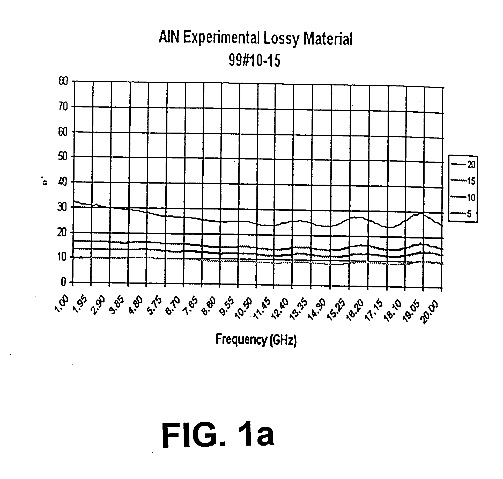
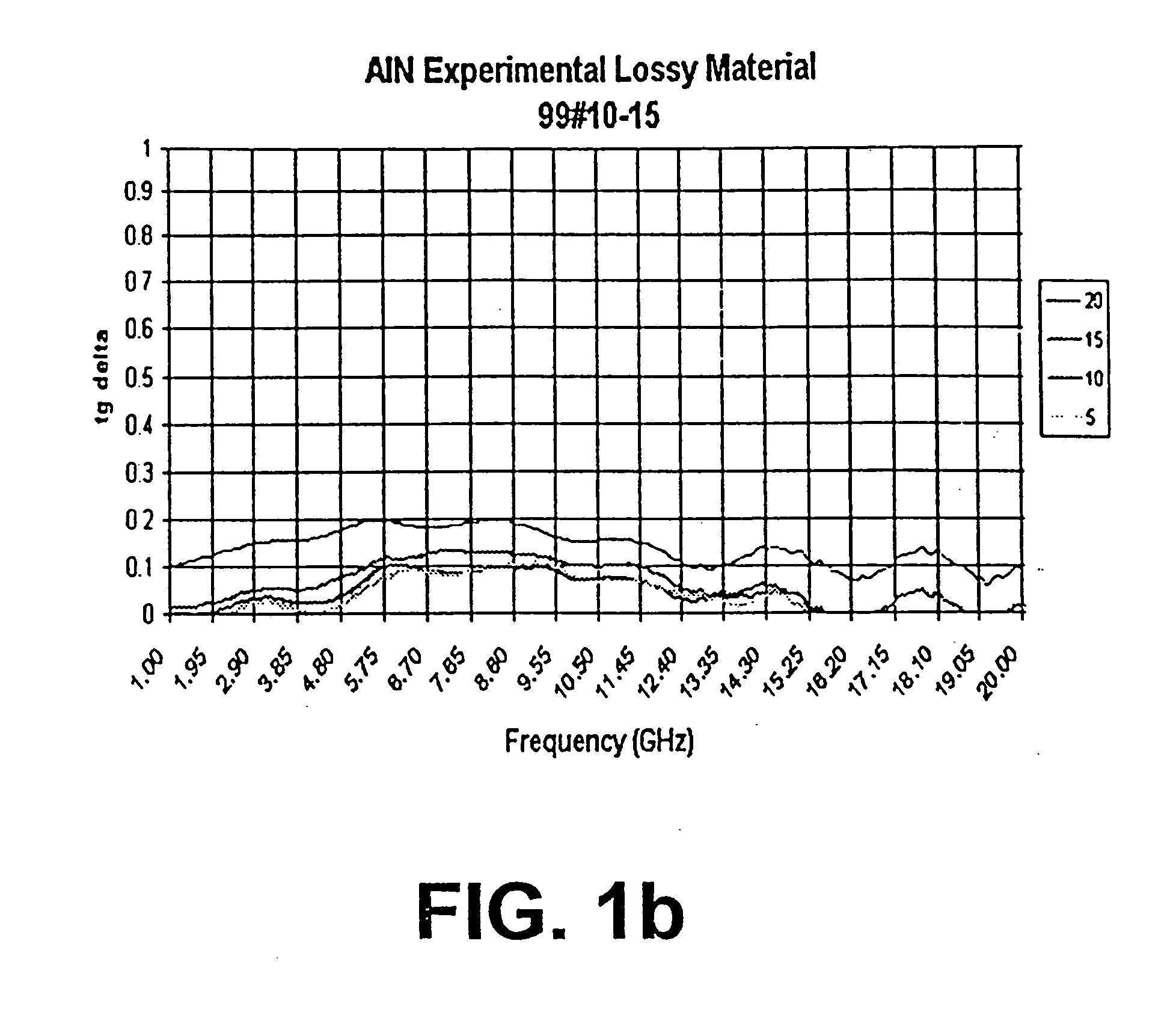
[0019] Several different samples of the composite material comprising of mixed AlN, ZrC and Y2O3 powders were formed using varying percentages of ZrC and Y2O3. Commercially available AlN, ZrC and Y2O3 powders were used. Powder mixing was accomplished using standard mixing techniques in a non-aqueous medium (isopropyl alcohol, hexane or similar). Powder was then dried, homogenized and screened. (Binders can be added to the powder, and the powder can be spray dried if required without deviating from the teachings of the invention.) The powder was then poured into a steel 4×4″ die, and uniaxially pressed to form a billet.

[0020] The billets were assembled into a graphite hot press die, and loaded into a hot pressing furnace. The billets were hot pressed in an inert atmosphere at temperatures from 1600-1950° C., and with applied pressures of 1000-4000 psi. The heating rates are dependent on the furnace and the load size, and temperatures holds in the 1650-1750° C. range are preferable i...

example 2

[0023] Several different samples of the composite material comprising mixed AlN, ZrC and Y2O3 powders were formed using varying percentages of ZrC and Y2O3. Commercially available AlN, ZrC and Y2O3 powders were used. Powder mixing was accomplished using standard mixing techniques in a non-aqueous medium (isopropyl alcohol, hexane or similar). Powder was then dried, homogenized and screened. (Binders can be added to the powder, and the powder can be spray dried if required without deviating from the teachings of the invention). The powder was then uniaxially pressed into pellets.

[0024] The pellets were subsequently pressureless sintered in a protective atmosphere at 1860° C. Table 2 shows that the resulting materials are lossy. It should be noted that further optimization of the raw powders, sintering temperature and material composition would result in improved material densities, but would not substantially alter the advantageous characteristics of the invention.

TABLE 2Pressurel...


PUM

PropertyMeasurementUnit
microwave frequenciesaaaaaaaaaa
frequencyaaaaaaaaaa
dielectric constantsaaaaaaaaaa

Abstract

An aluminum nitride (AlN), alumina, magnesia, beryllia or other dielectric matrix with a ZrC dispersed phase is provided. Mixed powders of aluminum nitride or other dielectric phases and ZrC, with or without Y2O3, CaO, Li2O, La2O3, and other rare earth metal oxides or mixtures thereof are formed by dry pressing (or isostatic pressing, injection molding or other similar methods known to those familiar with the art). Consolidation at high temperatures (and or pressures) to a virtually dense material with densities of over 95%, preferably higher than 97% of theoretical density can be attained by hot pressing, hip-ing, gas-pressure sintering or pressureless sintering (including microwave sintering). A controlled inert atmosphere is required to prevent the oxidation or other reaction of the carbide phase. Ar or similar atmosphere is preferred to avoid reactions with ZrC. Materials produced according to the invention can have real dielectric constants in at least the 8-40 range, with the loss tangents ranging from 0.01-0.3 at 2 GHz. The materials described have lossy properties over a wide frequency range (0.5 to over 20 GHz), and at temperatures from 2 K to above room temperature.

Description

BACKGROUND OF THE INVENTION [0001] 1. Field of the Invention [0002] The present invention relates generally to the field of ceramic materials and more specifically to tunable lossy dielectric ceramic materials especially useful at high frequencies and at low temperatures. [0003] 2. Background [0004] A limited number of high power particle accelerators (e.g., Continuous Electron Beam Accelerator Facility—CEBAF—at Jefferson National Accelerator Center, Newport News), operate at extremely low temperatures (2-4 K). For the accelerator's efficient operation, higher order mode (HOMs) microwave frequencies need to be damped (absorbed) at these temperatures. PRIOR ART [0005] A range of AlN, Al2O3, BeO, MgO composites with SiC particulates have been used in the electron device industry for damping microwave frequencies at room temperature. These materials have been found to be ineffective at cryogenic temperatures. [0006] In the early 1990's, Ceradyne, Inc. in collaboration with CEBAF (Newpo...

Claims


Application Information

Patent Timeline
Patent Type & Authority Applications(United States)
IPC IPC(8): C04B35/56C04B35/582
CPCC04B35/08C04B35/117C04B35/581C04B2235/3203C04B2235/3208C04B2235/3224C04B2235/77C04B2235/3227C04B2235/3839C04B2235/5409C04B2235/5436C04B2235/658C04B2235/3225
Inventor MIKIJELJ, BILJANA
Owner CERADYNE
Why Eureka
Try Eureka