Methods and apparatus for improved drilling and milling tools for resection

a drilling and milling tool technology, applied in the field of bone resection, can solve the problems of inability or high resistance of the disclosed tool embodiment, and achieve the effect of facilitating intraoperative and postoperative efficacy and ease of use, and minimizing the tendency of the pilot drill bi

Active Publication Date: 2006-01-19
BIOMET MFG CORP
View PDF99 Cites 91 Cited by
  • Summary
  • Abstract
  • Description
  • Claims
  • Application Information

AI Technical Summary

Benefits of technology

[0011] The present invention provides for embodiments of milling and drilling tools and soft tissue management techniques for arthroplasty facilitating intraoperative and postoperative efficacy and ease of use. In one embodiment, resiliently biased soft tissue protective sleeves surround the side cutting tool and are interposed along the longitudinal axis of the side cutting tool adjacent each side of the bone. The soft tissue protective sleeves are biased to track along the contour of the side of the bone and prevent the side cutting tool from being exposed to soft tissue during the resection. In another embodiment, a pilot drill is initially utilized to create an initial bore in the bone to be resected. The pilot drill preferably has an end cutting arrangement and a non-cutting removal channel that minimizes the tendency of the pilot drill bit to drift off-axis as the initial bore in the bone is created. Once the initial bore is created, the pilot drill bit is withdrawn and a second side cutting tool, such as a milling bit, is then inserted into the bore to perform the desired surface resection.

Problems solved by technology

Specifically, many of the cutting tool embodiments disclosed are either incapable or highly resistant to damaging soft tissue, or are by means disclosed prevented from coming into contact with soft tissue in the first place.

Method used


Image

  • Methods and apparatus for improved drilling and milling tools for resection
  • Methods and apparatus for improved drilling and milling tools for resection
  • Methods and apparatus for improved drilling and milling tools for resection

Examples


Embodiment Construction

[0022] It should be noted that, in many of the figures, the cut surface created by the cutting tool in accordance with the techniques of the present invention are shown as having already been completed for the sake of clarity. Similarly, the bones may be shown as being transparent or translucent for the sake of clarity. The guides / pins, cutting tool, bones, and other items disclosed are may be similarly represented for the sake of clarity or brevity

FIGS. 1 through 4

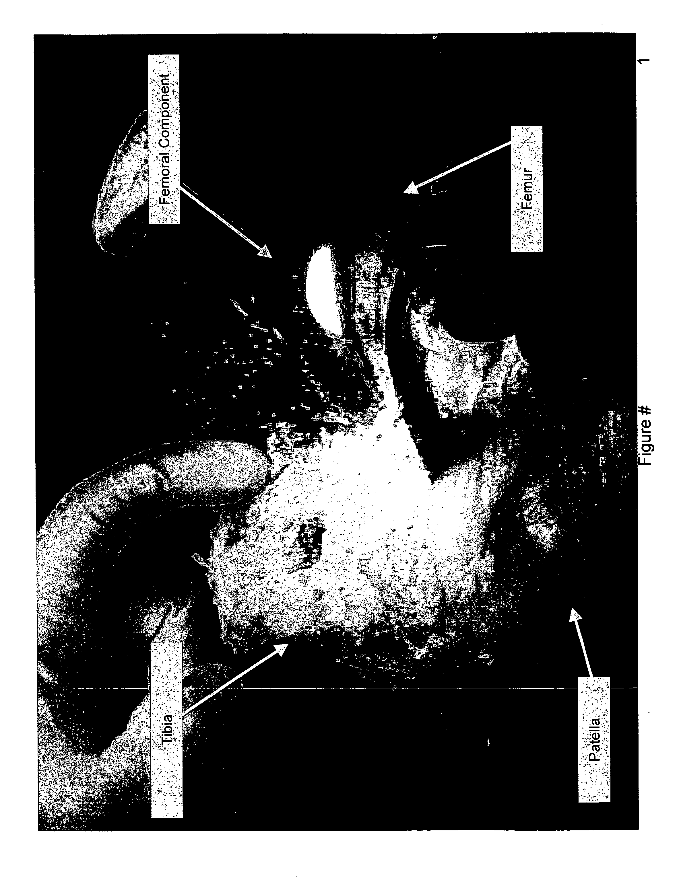
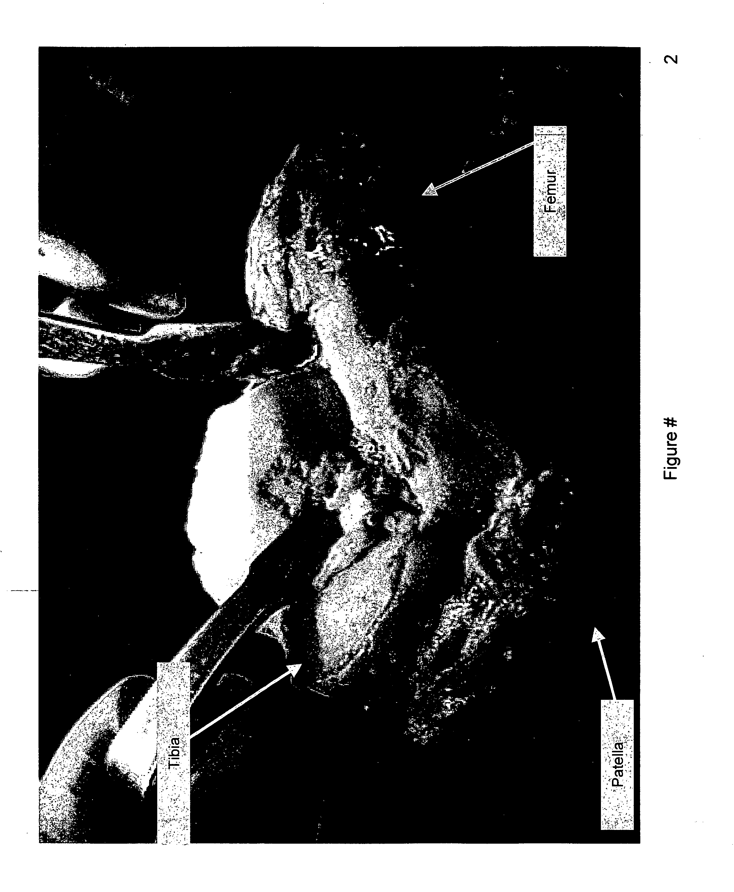
[0023]FIGS. 1 and 2 show conventional surgical exposures and instrumentation being utilized. FIG. 4 shows a reduced incision currently utilized in performing the current state of the art in ‘minimally invasive’ Unicondylar Knee Replacement.

FIGS. 41-60

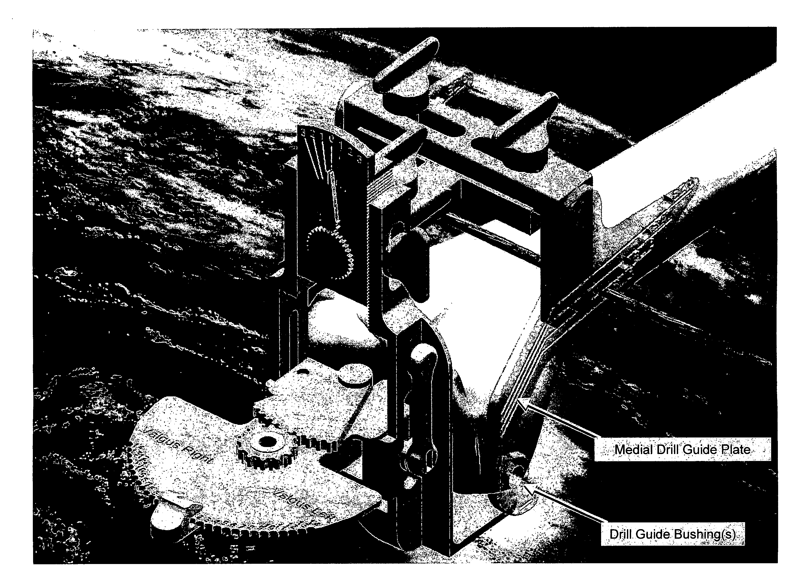
[0024]FIGS. 41 through 60 represent an embodiment of the present invention the soft tissue protection sleeves and milling / drilling bit management techniques that enable Triple Transcutaneous Transarticular TKA (“TTTKA” or “Triple TKA” or “T Cubed” or “T3” Procedures). The s...


PUM


Abstract

Milling and drilling tools and soft tissue management techniques are provided for arthroplasty that facilitate intraoperative and postoperative efficacy and ease of use. In one embodiment, resiliently biased soft tissue protective sleeves surround a side cutting tool and are interposed along the longitudinal axis of the cutting tool, preferably adjacent each side of the bone. The soft tissue protective sleeves are biased to track along the contour of the side of the bone and prevent the cutting tool from being exposed to soft tissue during the resection. In another embodiment, a pilot drill is initially utilized to create an initial bore in the bone to be resected. The pilot drill preferably has an end cutting arrangement and a non-cutting removal channel that minimizes the tendency of the pilot drill bit to drift off-axis as the initial bore in the bone is created. Once the initial bore is created, the pilot drill bit is withdrawn and a second side cutting tool, such as a milling bit, is then inserted into the bore to perform the desired surface resection.

Description

CLAIM TO PRIORITY [0001] The present invention claims priority to U.S. Provisional Application No. 60 / 551,262, filed Mar. 8, 2004, entitled, “METHODS AND APPARATUS FOR IMPROVED DRILLING AND MILLING TOOLS FOR RESECTION,” and U.S. Provisional Application No. 60 / 551,080, filed Mar. 8, 2004, entitled, “METHODS AND APPARATUS FOR PIVOTABLE GUIDE SURFACES FOR ARTHROPLASTY,” and U.S. Provisional Application No. 60 / 551,078, filed Mar. 8, 2004, entitled, “METHODS AND APPARATUS FOR MINIMALLY INVASIVE RESECTION,” and U.S. Provisional Application No. 60 / 551,096, filed Mar. 8, 2004, entitled, “METHODS AND APPARATUS FOR ENHANCED RETENTION OF PROSTHETIC IMPLANTS,” and U.S. Provisional Application No. 60 / 551,631, filed Mar. 8, 2004, entitled, “METHODS AND APPARATUS FOR CONFORMABLE PROSTHETIC IMPLANTS,” and U.S. Provisional Application No. 60 / 551,307, filed Mar. 8, 2004, entitled, “METHODS AND APPARATUS FOR IMPROVED CUTTING TOOLS FOR RESECTION,” and U.S. Provisional Application No. 60 / 551,160, filed ...

Claims


Application Information

Patent Timeline
Patent Type & Authority Applications(United States)
IPC IPC(8): A61B17/58
CPCA61B17/15A61B17/155A61B17/157A61B17/1671A61B17/1675A61F2310/00011A61B17/1764A61B2017/1602A61F2/38A61F2/3859A61F2002/3895A61B17/1757
Inventor HAINES, TIMOTHY G.
Owner BIOMET MFG CORP
Why Eureka
Try Eureka