Method of producing low profile stent and graft combination

a low-profile, graft technology, applied in the field of endoprosthetic devices, can solve the problems of limiting tissue encroachment into the device, increasing the risk of infection, and affecting the effect of treatment,

Inactive Publication Date: 2006-01-19
WL GORE & ASSOC INC
View PDF98 Cites 31 Cited by
  • Summary
  • Abstract
  • Description
  • Claims
  • Application Information

AI Technical Summary

Benefits of technology

[0027] Further advantages of the present invention are to provide a very low profile covered-stent, and to provide a covered-stent with the broadest deployment range, from the delivery size to the fully extended (i.e., deployed) size. Still another advantage of the present invention is the ability to create very small implantable devices that are capable of being delivered in extremely small compacted dimensions. These and other benefits of the present invention will be appreciated from review of the following description.
is the ability to create very small implantable devices that are capable of being delivered in extremely small compacted dimensions. These and other benefits of the present invention will be appreciated from review of the following description.

Problems solved by technology

When a defect, such as an aneurysm, is located very close to the bifurcation of a trunk into two branches, treatment becomes especially difficult.
Second, covered devices can also limit tissue encroachment into the device over time.
While covered stent devices have many benefits, unfortunately current covered-stents used for the treatment of disease of large vessels (e.g., thoracic or abdominal aortic vessels) generally require a surgical incision to provide a large enough access site to deliver such devices.
Virtually all such devices currently are too large for less-invasive percutaneous delivery.
As has been noted, percutaneous delivery is almost always preferred but is difficult or impossible to achieve for larger devices.
There are many problems encountered in attempting to compact a device into its smallest deliverable dimensions.
If a graft component is added, this further increases the bulk of the device.
Second, all known stent element designs provide the stent with crush-resistance (which is required if the stent is to have any structural value in holding open a vessel).
This resistance to crushing further confounds attempts to tightly compact the device—with the risk that over-compacting the stent may damage its crush-resistance (and thus its structural value as a stent).
On the other hand, less resilient stent devices might be more receptive to compaction, but are less effective in holding open the vessel once deployed.
Third, the graft material is also at risk of damage during compacting.
Fourth, any compaction of a stent or stent-graft will likely tend to reduce the flexibility of the compacted device.
Extreme compaction may produce a compacted device that is so inflexible that it will not negotiate tortuous paths in the body.
Sixth, there are covered stents available today that can be compressed into small delivery profiles, but these devices undergo extreme elongation in their compressed state, with extreme foreshortening when transitioned to their deployed dimensions.
These extremes in device length between compact and deployed dimensions make these devices difficult to properly position and deploy.
Additionally, these devices tend to have less resilient stent structures.
Finally, perhaps the greatest deficiency of these devices is that they must be covered with a material that can likewise undergo extreme elongation and contraction to match the longitudinal behavior of the stent element.
As a result, preferred biocompatible graft materials such as polytetrafluoroethylene (PTFE) and woven DACRON® polyester are not readily used on these devices since neither is capable of extreme stretching and rebounding.
Although these devices can fit through smaller delivery sites of 8 to 10 F, exact placement is often difficult because of the significant longitudinal retraction or recoil of the stent graft as it reaches its deployed size.
The design of this stent relies on extreme elongation to achieve its compaction, hence undesirable foreshortening of the device naturally occurs during deployment.
As a result, this design cannot accommodate a longitudinal strength member that would resist elongation during compaction of the device.
The coverings primarily serve as a barrier to the passage of blood and / or tissue or other elements in use, although their stretch and recovery requirements severely limit they types of materials that can be used in this device.
Thickness and porosity is also a design limitation for these elastomeric stent coverings.
To reduce porosity the coverings often must be thicker (often about 0.05 mm or greater), which can adversely effect delivery profile.
However, there currently are a number of serious constraints limiting the ability to compact endoprosthetic devices, and particularly large vessel endoprosthetic devices (for instance, for treatment of aortic diseases and trauma), into their smallest possible delivery profiles.

Method used


Image

  • Method of producing low profile stent and graft combination
  • Method of producing low profile stent and graft combination
  • Method of producing low profile stent and graft combination

Examples


example 1

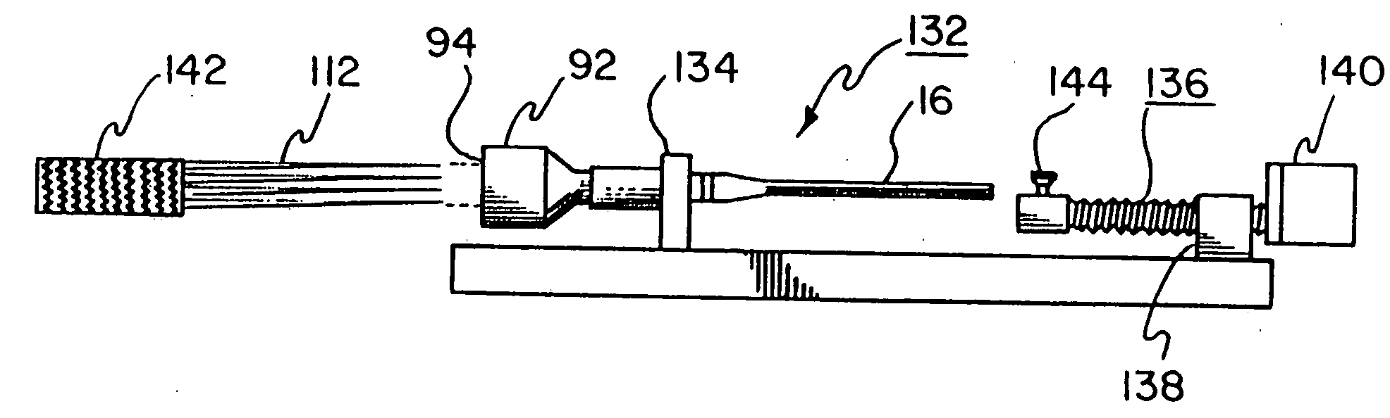
[0127] A 40 mm inner diameter thoracic aortic stent-graft is created. The stent portion is built using 0.30 mm diameter, 40-45% cold worked NiTi (nitinol) wire (SE 508; Nibnol Devices & Components, Fremont, Calif.) formed using a mandrel with protruding pins. The stent is constructed using a single wire, creating an undulating, helical, tubular stent member by winding the wire on a pin fixture as described in the above-mentioned published PCT patent application. See FIGS. 7 through 9.

[0128] Once the wire is formed on the pin fixture, it is heat treated in a convection oven set at 450° C. for 15 minutes. After removal from the oven and quenching in a water bath, the wire frame is unwound from the fixture creating a freestanding tubular stent frame.

[0129] The stent cover is constructed from a strong, thin film. A suitable film comprises expanded PTFE (ePTFE) film made in accordance with the teachings of U.S. Pat. No. 5,476,589 to Bacino, incorporated by reference. This expanded PTFE...

example 2

[0139] Another 40 mm inner diameter thoracic aortic stent-graft is constructed using polyester as the stent covering material. The stent portion is constructed using 0.20 mm diameter nitinol wire (SE 508; 40-45% cold worked; Nitinol Devices & Components, Fremont, Calif.). Yellow polyester film (PES 30 / 25, available from Saatitech, Inc., Somers, N.Y.) is employed as the stent covering. The polyester material is approximately 0.046 mm thick. The stent member is formed and heat treated in the manner described above in Example 1. The stent covering is attached to the inner surface of the stent frame with CV-8 Sutures (available from W.L. Gore & Associates, Inc., Flagstaff, Ariz.), using a running stitch and tying the ends of the of the sutures together.

[0140] As in Example 1, the device is pulled down into a tapered fixture and contained within a capture tube containing a removable polyester inner liner. A 0.89 mm guidewire is inserted inside the stent-graft prior to compaction. A long...

example 3

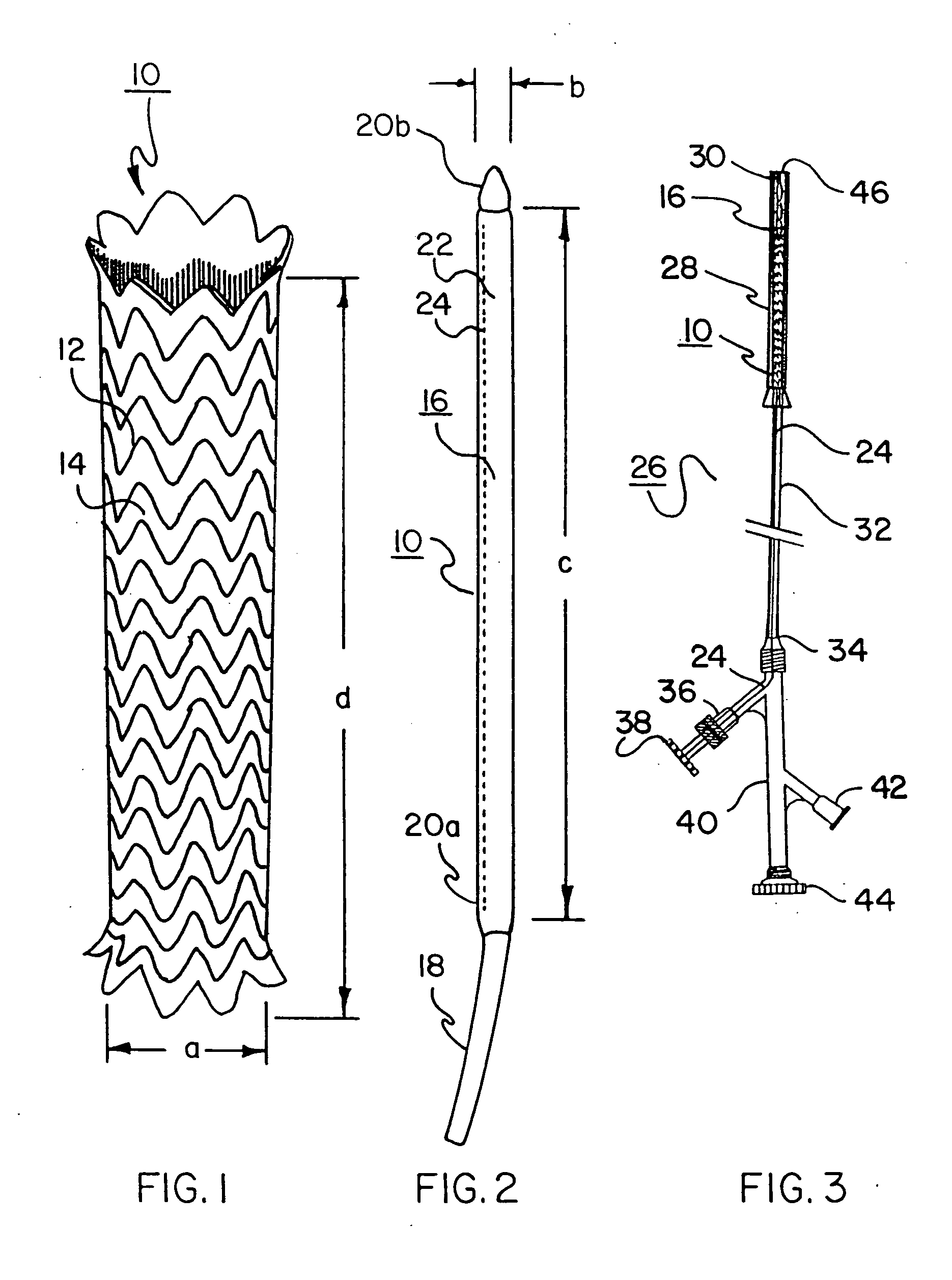
[0142] A 26 mm inner diameter thoracic aortic stent-graft is constructed using 0.20 mm nitinol wire (SE 508; 40-45% cold worked; Nitinol Devices & Components, Fremont, Calif.) and ePTFE film. This stent-graft is made in the same manner, with the same materials, as described in Example 1 following the steps outlined in Table 1. The device is drawn down over a 0.89 mm diameter wire to simulate the presence of a guidewire. The stent-graft and wire are pulled into a polyester tube (fabricated as described in Example 1). The stent-graft plus polyester tube fits within a 6 F hole. The stent-graft deploys to 24 mm in a 36° C. water bath. Gently pulling the stent-graft over a tapered mandrel deploys the device to 26 mm.

[0143] The a:b ratio for this device is 13.3:1.


PUM

PropertyMeasurementUnit
diameteraaaaaaaaaa
diameteraaaaaaaaaa
diametersaaaaaaaaaa

Abstract

Large diameter self-expanding endoprosthetic devices, such as stents and stent grafts for delivery to large diameter vessels, such as the aorta, are disclosed having very small compacted delivery dimensions. Devices with deployed dimensions of 26 to 40 mm or more are disclosed that are compacted to extremely small dimensions of 5 mm or less, enabling percutaneous delivery of said devices without the need for surgical intervention. Compaction efficiencies are achieved by combining unique material combinations with new forms of restraining devices, compaction techniques, and delivery techniques. These inventive devices permit consistent percutaneous delivery of large vessel treatment devices. Additionally, small endoprosthetic devices are disclosed that can be compacted to extremely small dimensions for delivery through catheter tubes of less than 1 mm diameter.

Description

CROSS REFERENCE TO RELATED APPLICATIONS [0001] The present application is a division of co-pending U.S. patent application Ser. No. 10 / 083,451 filed Feb. 25, 2002 which is a division of Ser. No. 09 / 235,458, filed Jan. 22, 1999 (abandoned).BACKGROUND OF THE INVENTION [0002] 1. Field of the Invention [0003] The present invention relates to methods of producing endoprosthetic devices, such as stents and stent-grafts, that are used to repair and / or treat diseased or damaged vessels and other structures within a body, and particularly to such devices that can be introduced at small delivery profiles and then enlarged in place. [0004] 2. Description of Related Art [0005] Stents and stent-grafts are used in the treatment of vascular and other disease. They are particularly useful for treatment of vascular or arterial occlusion or stenosis typically associated with vessels narrowed by disease. Intraluminal stents and stent-grafts function to hold these vessels open mechanically. In some ins...

Claims


Application Information

Patent Timeline
Patent Type & Authority Applications(United States)
IPC IPC(8): A61F2/06A61F2/82A61F2/86A61F2/90
CPCA61F2/07Y10T29/53987A61F2/86A61F2/90A61F2/91A61F2/954A61F2/97A61F2002/067A61F2002/072A61F2002/075A61F2002/825A61F2002/9505A61F2002/9511A61F2002/9522A61F2/89A61F2230/0054A61F2220/0075A61F2/844A61F2/9522A61F2/9525
Inventor ARMSTRONG, JOSEPH R.CULLY, EDWARD H.ULM, MARK J.VONESH, MICHAEL J.
Owner WL GORE & ASSOC INC
Why Eureka
Try Eureka