Vehicle control system

a control system and vehicle technology, applied in the direction of driver input parameters, external condition input parameters, electric devices, etc., can solve the problems of increasing cost, sophisticated processing, and inability to perform any maneuvering of the vehicle, and achieves low cost, simplified ecu configuration, and high reliability

Active Publication Date: 2006-01-19
HITACHI ASTEMO LTD
View PDF4 Cites 174 Cited by
  • Summary
  • Abstract
  • Description
  • Claims
  • Application Information

AI Technical Summary

Benefits of technology

[0011] The above-mentioned vehicle control system is generally known as the “X-by-Wire” system and is expected to realize more intelligent integrated running control, to reduce the vehicle weight, and to increase the flexibility in design by using a computer in comparison with the known system transmitting control forces through mechanical and hydraulic mechanisms.

Problems solved by technology

Therefore, if the master ECU is failed, the maneuvering of the vehicle cannot be performed at all.
However, redundancy of the master ECU requiring sophisticated processing increases the cost.

Method used


Image

  • Vehicle control system
  • Vehicle control system
  • Vehicle control system

Examples


first embodiment

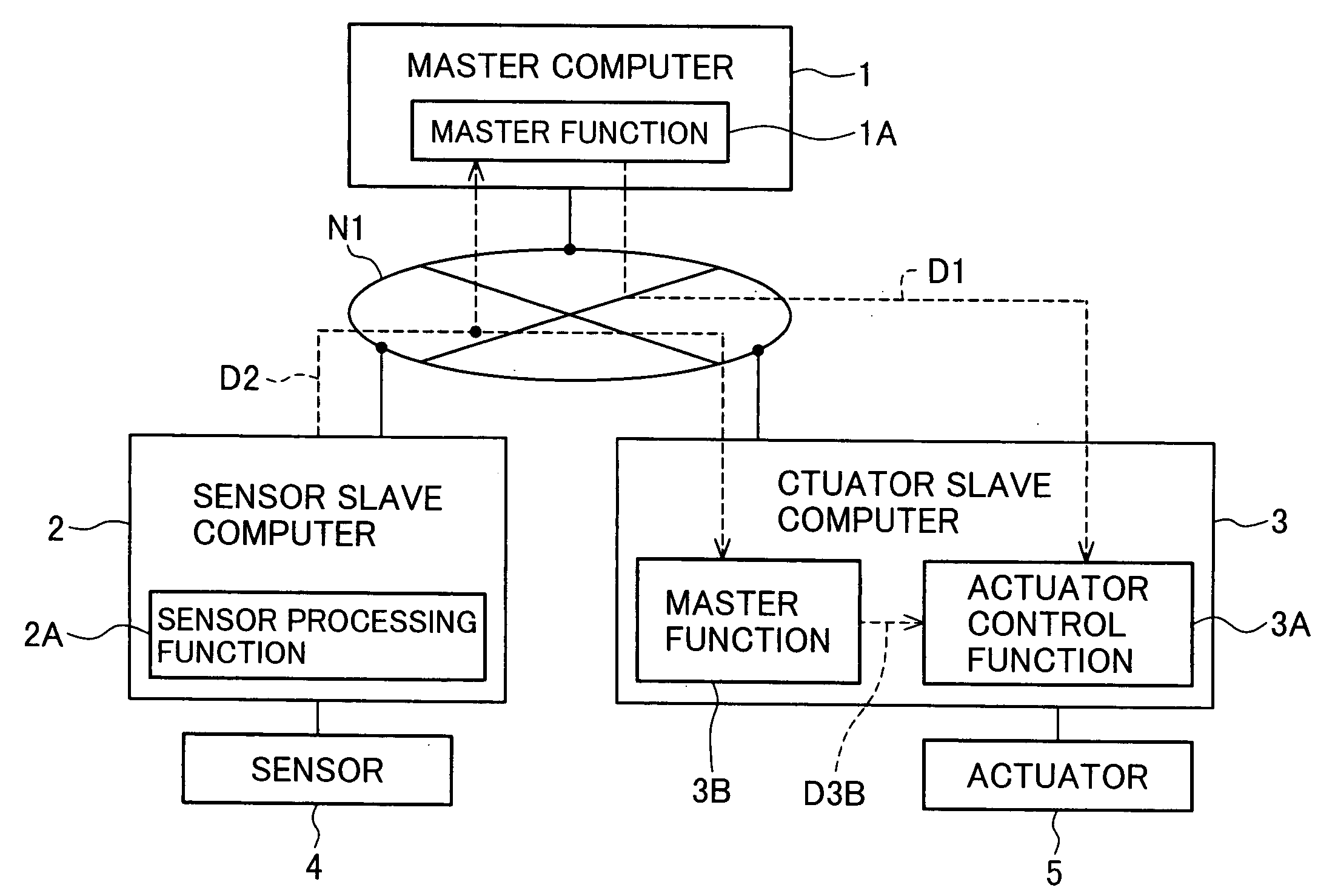
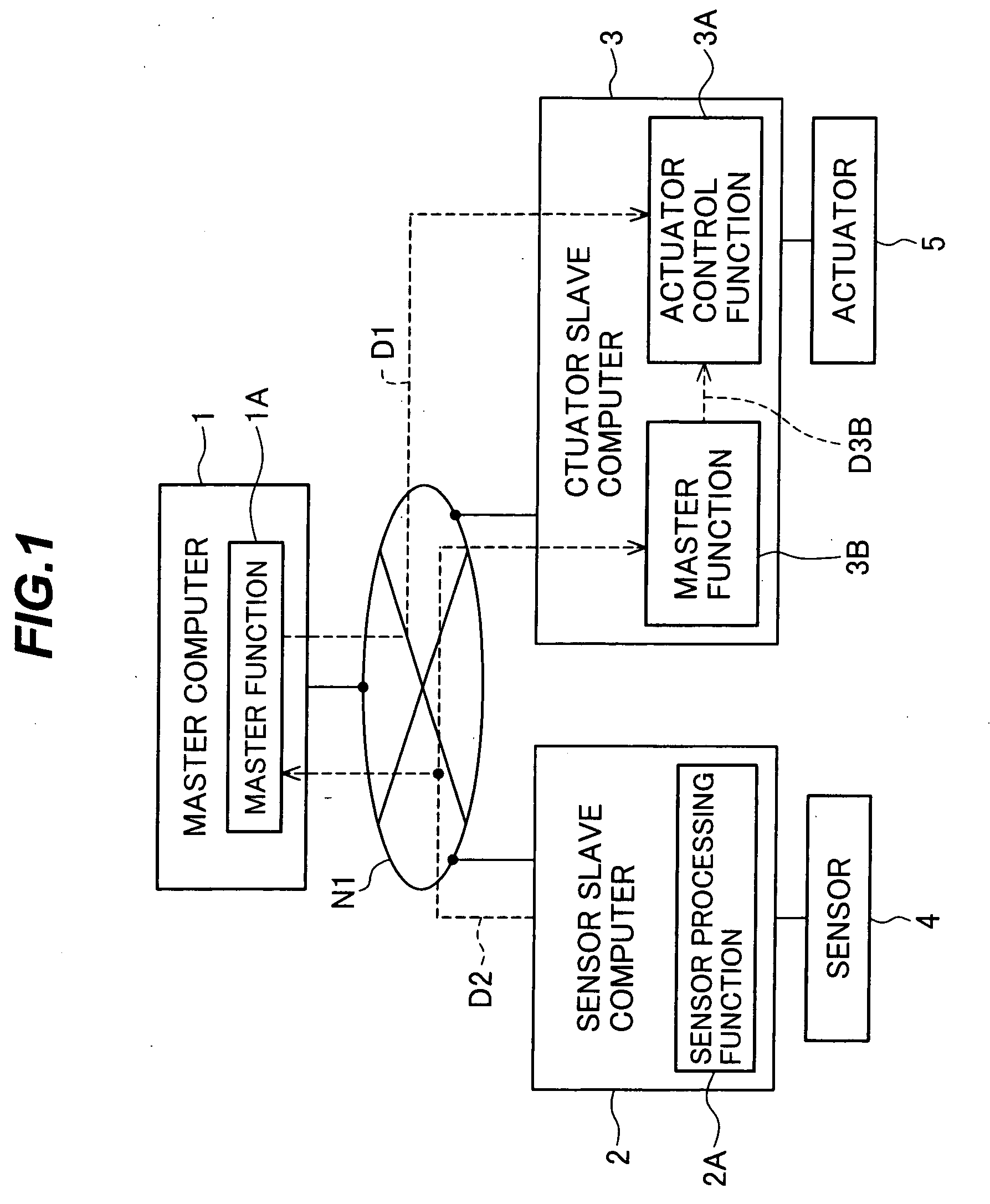
[0131] First, a basic configuration of a vehicle control system according to a first embodiment of the present invention will be described below with reference to FIG. 1.

[0132] The vehicle control system comprises a master computer (command controller) 1, a sensor slave computer (sensor controller) 2, and an actuator slave computer (actuator controller) 3. These computers are interconnected to perform two-way data communication among them via a wired or wireless network N1 of bus, mesh, star, ring or any other suitable type.

[0133] The master computer 1 is a command controller for computing a control target value and includes a master control function (master control means) 1A.

[0134] The sensor slave computer 2 is connected to a sensor 4 for monitoring (measuring) the status of a control target. The sensor slave computer 2 includes a sensor processing function (sensor processing means) 2A for processing a sensor signal from the sensor 4.

[0135] An actuator 5 for operating the cont...

second embodiment

[0243] An autonomous decentralized control platform oriented for an integrated vehicle control system in a next-generation vehicle, to which the vehicle control system according to the present invention is applied, will be described below with reference to FIG. 13.

[0244] The purpose of the autonomous decentralized control platform is to realize high reliability, real-time processing, and expandability in vehicle control at a low cost.

[0245] The term “autonomous decentralized” means one of highly reliable decentralized system models used in the control field. In other words, it represents a system in which computing nuclei called nodes corresponding to cells in an organism are loosely coupled with one another via a field, called a data field, where common data is placed.

[0246] For details of “autonomous decentralized”, reference should be made on Kinji Mori, Tsugu Miyamoto, and Koichi Ihara; “Proposal of Autonomous Decentralized Concept”, Journal C of the Institute of Electrical E...

third embodiment

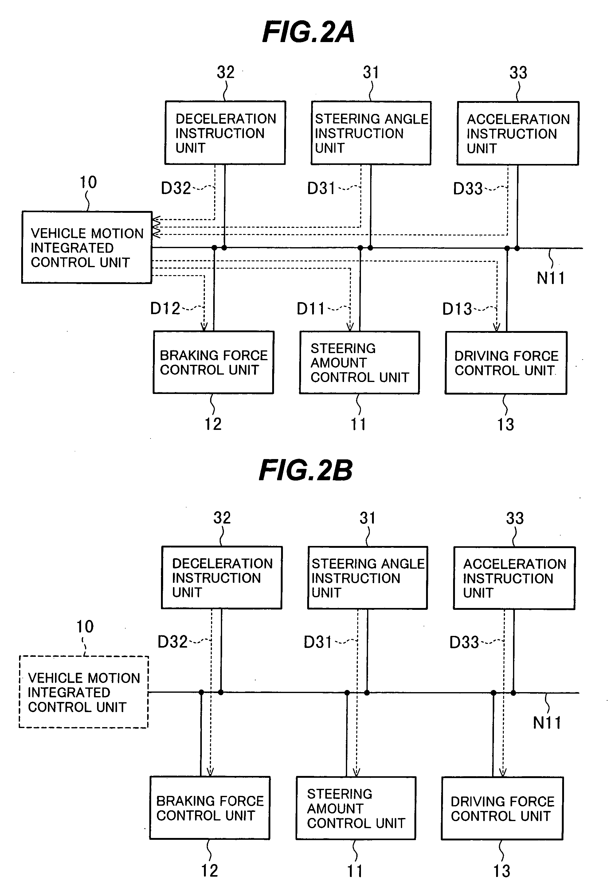
[0316] A vehicle control system according to a third embodiment of the present invention will be described below with reference to FIG. 22. FIG. 22 shows an extracted portion of the vehicle control system, which is in particular related to the brake control and the steering control.

[0317] The vehicle control system of this embodiment includes, as sensors for detecting the driver's demands, a steering angle sensor 41 for measuring the rotational angle of a steering wheel 51 and a brake pedal position sensor 42 for measuring the step-down amount of a brake pedal 52. Also, the vehicle control system includes, as an operation amount generating node, a vehicle motion integrated control ECU 30 for interpreting the driver's intent based on signals from the driver's demand detecting sensors and for controlling the vehicle motion in an integrated manner in combination with signals from other sensors (not shown) for detecting the vehicle status, such as an acceleration sensor, a yaw rate sen...


PUM


Abstract

A vehicle control system which can ensure high reliability, real-time processing, and expandability with a simplified ECU configuration and a low cost by backing up an error through coordination in the entire system without increasing a degree of redundancy of individual controllers beyond the least necessary level. The vehicle control system comprises a sensor controller for taking in sensor signals indicating a status variable of a vehicle and an operation amount applied from a driver, a command controller for generating a control target value based on the sensor signals taken in by the sensor controller, and an actuator controller for receiving the control target value from the command controller and operating an actuator to control the vehicle, those three controller being interconnected via a network. The actuator controller includes a control target value generating unit for generating a control target value based on the sensor signals taken in by the sensor controller and received by the actuator controller via the network when the control target value generated by the command controller is abnormal, and controls the actuator in accordance with the control target value generated by the control target value generating unit.

Description

BACKGROUND OF THE INVENTION [0001] 1. Field of the Invention [0002] The present invention relates to a vehicle control system for controlling the running state of a vehicle. More particularly, the present invention relates to a vehicle control system for electronically controlling driving of a prime mover, steering and braking in a vehicle such as an automobile. [0003] 2. Description of the Related Art [0004] As a vehicle control system, there was hitherto known an operation control system for controlling various control means related to a braking force, a driving force and a steering angle by an electronic control system, i.e., one master, in a concentrated manner (see, e.g., Patent Reference 1: JP-A-2003-263235). [0005] Recently, aiming at an improvement of comfortableness in driving and safety of an automobile, a vehicle control system has intensively been developed in which driver's operations on an accelerator, a steering wheel and a brake are reflected on mechanisms for genera...

Claims


Application Information

Patent Timeline
Patent Type & Authority Applications(United States)
IPC IPC(8): G06F19/00B60K31/04B60T7/12B60W10/10B60W10/18B60W40/08B60W40/10B60W50/02B62D6/00
CPCB60K6/46Y02T10/6286B60W10/04B60W10/06B60W10/08B60W10/10B60W10/18B60W10/20B60W20/00B60W40/08B60W40/10B60W50/02B60W50/0225B60W50/04B60W2510/20B60W2510/202B60W2520/14B60W2540/10B60W2540/12B60W2550/20B62D5/0481G06F11/0796Y02T10/6217Y02T10/6265B60K6/52B60L3/0023B60L3/003B60L3/0076B60L3/0092B60L15/2009B60L2240/12B60L2240/20B60L2240/24B60L2240/423B60L2250/26B60W2540/18B60W2554/00Y02T10/62Y02T10/64Y02T10/72Y02T90/16B60T7/12B60W30/00B62D5/046B62D6/00
Inventor YOSHIMURA, KENTAROSAKURAI, KOHEIKANEKAWA, NOBUYASUMORITA, YUICHIROTAKAHASHI, YOSHIAKIKUROSAWA, KENICHIMINOWA, TOSHIMICHIHOSHINO, MASATOSHINAKATSUKA, YASUHIROSHIMAMURA, KOTAROTSUNEDOMI, KUNIHIKOSASAKI, SHOJI
Owner HITACHI ASTEMO LTD
Why Eureka
Try Eureka