Turbocharger recirculation valve

a technology of recirculation valve and turbocharger, which is applied in the direction of air cleaners for fuel, combustion engines, machines/engines, etc., can solve the problems of engine to cease from operating completely, blockage of filters and/or ducts, and adverse effect on the locomotiv

Inactive Publication Date: 2006-01-26
GENERAL ELECTRIC CO
View PDF3 Cites 23 Cited by
  • Summary
  • Abstract
  • Description
  • Claims
  • Application Information

AI Technical Summary

Benefits of technology

[0009] A method for controlling operating characteristics of a locomotive engine having a turbocharger system relative to a surge operation of the turbocharger, wherein the locomotive engine is subject to operation at high altitude and low ambient temperatures, is provided and including directing an ambient air stream flow having an ambient air stream flow temperature into the turbocharger system to create a compressed air stream flow having a compressed air stream temperature higher than the ambient air stream temperature, directing a first portion of the compressed air to an intercooler device to create an intercooler air stream having an intercooler air stream temperature lower than the compressed air stream temperature, directing a second portion of at least one of the compressed air and the intercooler air toward a controllable re-circulation valve, wherein the controllable re-circulation valve is in flow communication with at least one of the compressed air stream flow and the ambient air stream flow and opening the re-circulation valve to combine the second portion of at least one of the compressed air and the intercooler air with at least one of the compressed air stream flow and the ambient air stream flow to reduce the discharge pressure of the compressed air from the turbocharger to change the operating characteristics of the engine and turbocharger so as to avoid surge operation of the turbocharger.

Problems solved by technology

Locomotives operated at high altitudes and in the far northern and southern regions of the globe are subject to severe environmental conditions which may have an adverse affect on the locomotive, including low atmospheric pressure, cold temperatures, and blowing and drifting snow.
One problem involves blockage of the filters and / or ducts.
It is known that snow may be drawn into the air inlet ducts of a locomotive and may accumulate in sufficient quantities to obstruct the passage of air through the ducts.
Such accumulations of snow may act to reduce the power output of the engine and / or may cause the engine to cease from operating completely.
Another problem involves the control of cylinder pressure to prevent the de-rating of the Gross Horse Power (GHP) on cold days.
This is undesirable because it increases the engine component stress and loading.
Another problem involves the surge margin (or engine stability limit) under cold ambient conditions and a high Manifold Air Temperature (MAT).
This is often made worse at high altitudes.

Method used


Image

  • Turbocharger recirculation valve
  • Turbocharger recirculation valve
  • Turbocharger recirculation valve

Examples


first embodiment

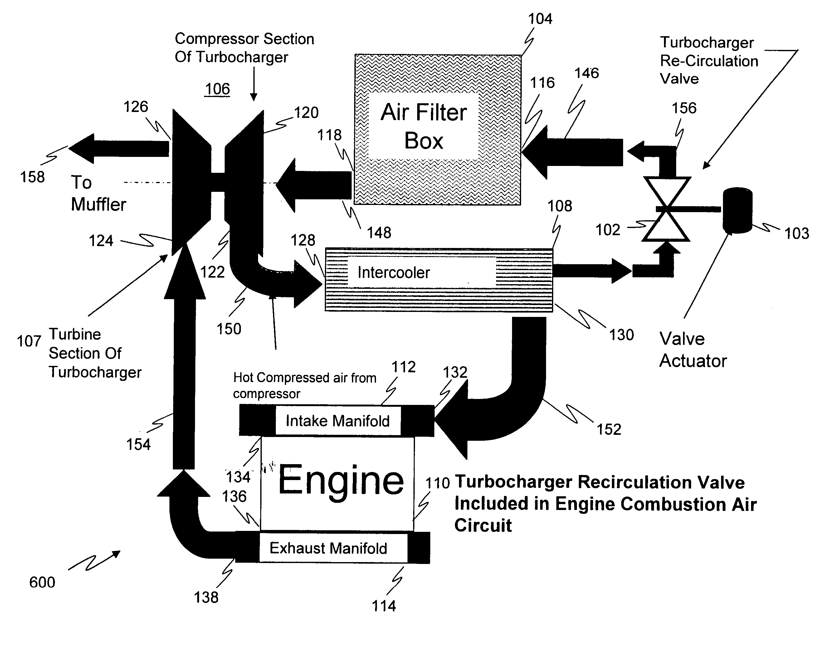
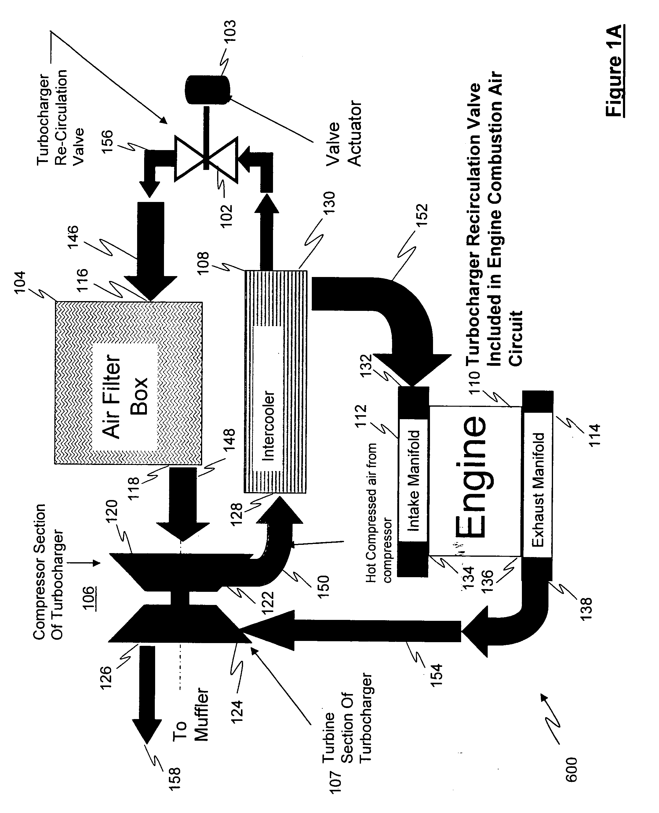
[0018] Referring to FIG. 1A, a schematic block diagram representing a locomotive turbocharger system 100 is shown and includes a turbocharger re-circulation valve 102 having a valve actuation device 103, an air filter box 104, a turbocharger compressor portion 106, a main intercooler device 108 and a locomotive engine 110, wherein locomotive engine 110 includes an intake manifold 112 and an exhaust manifold 114. Air filter box 104 includes an air inlet 116 and an air outlet 118, turbocharger compressor portion 106 includes a turbocharger compressor inlet 120, a turbocharger compressor outlet 122, a turbocharger turbine exhaust inlet 124 and a turbocharger turbine exhaust outlet 126. Main intercooler device 108 includes a main intercooler inlet 128 and a main intercooler outlet 130. Intake manifold 112 includes an intake inlet 132 and an intake outlet 134 and exhaust manifold 114 includes an exhaust inlet 136 and an exhaust outlet 138. In this embodiment, the main intercooler outlet ...

second embodiment

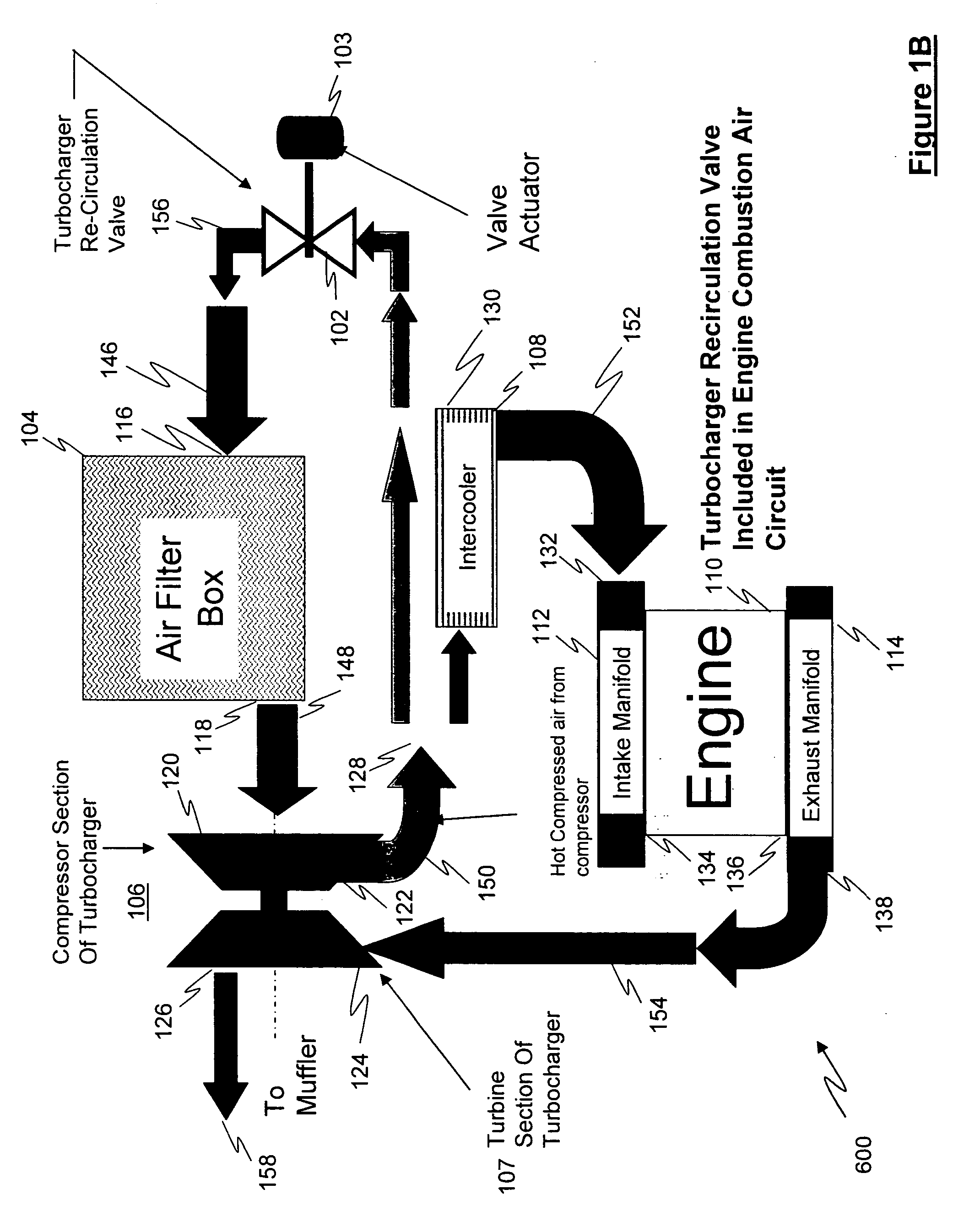
[0019] Referring to FIG. 1B, a schematic block diagram representing a locomotive turbocharger system 100 is shown and includes a turbocharger re-circulation valve 102 having a valve actuation device 103, an air filter box 104, a turbocharger compressor portion 106, a main intercooler device 108 and a locomotive engine 110, wherein locomotive engine 110 includes an intake manifold 112 and an exhaust manifold 114. Air filter box 104 includes an air inlet 116 and an air outlet 118, turbocharger compressor portion 106 includes a turbocharger compressor inlet 120, a turbocharger compressor outlet 122, a turbocharger turbine exhaust inlet 124 and a turbocharger turbine exhaust outlet 126. Main intercooler device 108 includes a main intercooler inlet 128 and a main intercooler outlet 130. Intake manifold 112 includes an intake inlet 132 and an intake outlet 134 and exhaust manifold 114 includes an exhaust inlet 136 and an exhaust outlet 138. In contrast to FIG. 1A, in this embodiment, the ...


PUM


Abstract

A system and method for maintaining an airflow path to a turbocharger system on a locomotive operating at high altitude and in a low ambient temperature environment, is provided and includes generating an ambient air stream flow into the turbocharger system to create a compressed air stream flow having a compressed air stream temperature, wherein the ambient air stream flow includes an ambient air stream flow temperature, processing the compressed air stream to create an intercooler air stream having an intercooler air stream temperature, wherein the compressed air stream temperature is greater than the intercooler air stream temperature, directing at least a portion of at least one of the compressed air stream and the intercooler air stream toward a controllable re-circulation device, wherein the controllable re-circulation device is communicated with at least one of the compressed air stream flow and the ambient air stream flow, operating the controllable re-circulation device to combine the at least a portion of at least one of the compressed air stream and the intercooler air stream with at least one of the compressed air stream flow and the ambient air stream flow to increase at least one of the compressed air stream temperature and the ambient air stream temperature to a predetermined level.

Description

RELATED APPLICATIONS [0001] This application claims priority from U.S. Provisional Patent Application No. 60 / 590,495 filed Jul. 23, 2004, the contents of which are hereby incorporated by reference herein.FIELD OF THE INVENTION [0002] The present invention relates generally to an internal combustion engine for a locomotive and, more particularly, to the recirculation of air to reduce the adverse effects of ambient air temperature changes on the performance of the engine. BACKGROUND OF THE INVENTION [0003] Locomotives operated at high altitudes and in the far northern and southern regions of the globe are subject to severe environmental conditions which may have an adverse affect on the locomotive, including low atmospheric pressure, cold temperatures, and blowing and drifting snow. [0004] One problem involves blockage of the filters and / or ducts. It is known that snow may be drawn into the air inlet ducts of a locomotive and may accumulate in sufficient quantities to obstruct the pas...

Claims


Application Information

Patent Timeline
Patent Type & Authority Applications(United States)
IPC IPC(8): F02B29/04F02B33/44
CPCF02B29/04F02B33/44Y02T10/144F02M35/04F02B37/16Y02T10/12
Inventor SWENSON, KENDALL ROGERMARSH, GREGORY ALAN
Owner GENERAL ELECTRIC CO
Why Eureka
Try Eureka