Pressure sensor

a technology of pressure sensor and sensor body, which is applied in the direction of fluid pressure measurement using elastically deformable gauges, instruments, fluid pressure measurement by mechanical elements, etc., can solve the problems of poor weldability and likely hot cracks, and achieve the effect of simple structure and enhanced weldability

Active Publication Date: 2006-01-26
NAGANO KEIKI
View PDF5 Cites 16 Cited by
  • Summary
  • Abstract
  • Description
  • Claims
  • Application Information

AI Technical Summary

Benefits of technology

[0019] In the present invention, since Ni content of the weld portion can be adjusted by bringing the cylindrical filler metal with an intercommunicating hole at the center thereof into contact with the portion to be welded and adjusting the weld depth in welding, the welding can be performed with a simple structure. Also, by adjusting Ni content of the weld portion to be in the range from 20 to 30 wt %, the weldability can be enhanced.

Problems solved by technology

Generally, the austenitic stainless steel and the austenitic precipitation hardening Fe—Ni heat resisting steel exhibit poor weldability, and thus a hot crack likely occurs.

Method used


Image

  • Pressure sensor
  • Pressure sensor
  • Pressure sensor

Examples


first embodiment

Advantage of First Embodiment

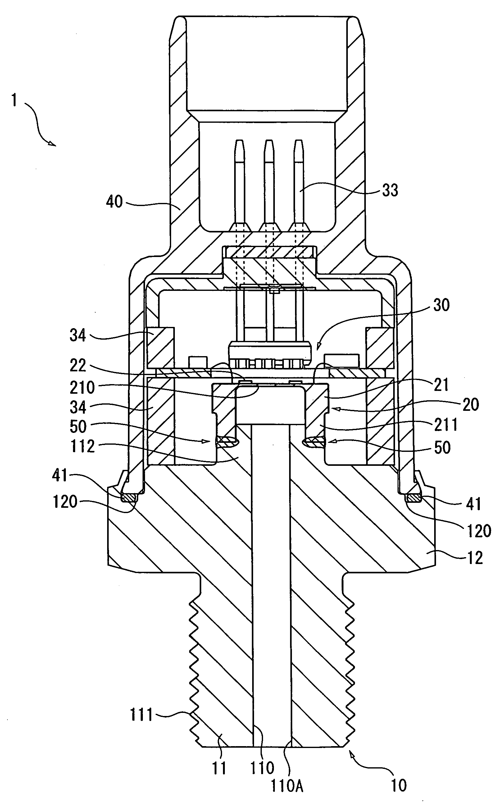
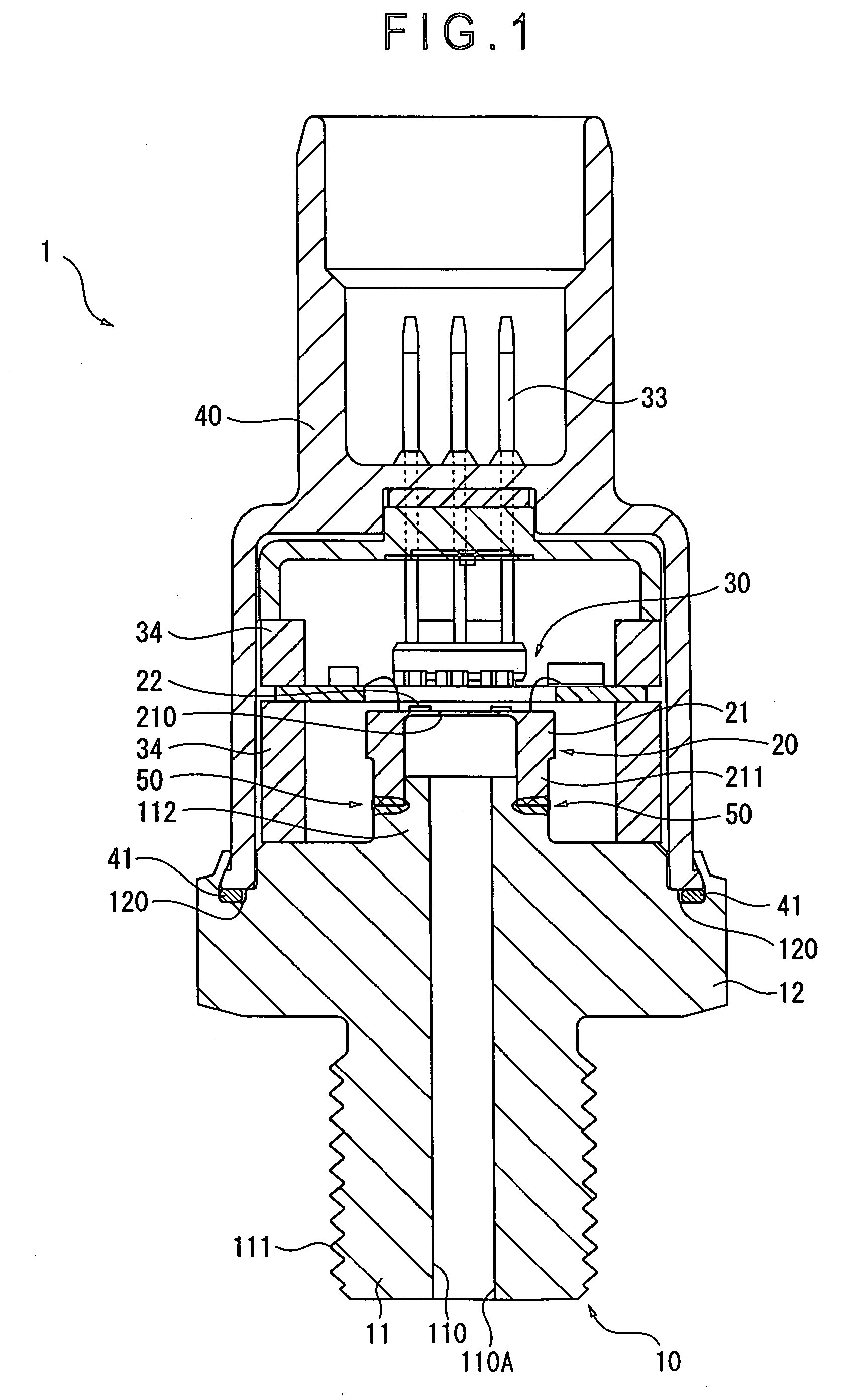
[0049] With the pressure sensor 1 of the pressure sensor 1 of the first embodiment of the present invention, the following advantages can be obtained.

[0050] (1) Since the austenitic precipitation hardening Fe—Ni heat resisting steel having high mechanical strength is used for the diaphragm 21 with the thin-wall portion 210 on the bottom, the thin-wall portion 210 can be produced to be thin, so that a high strain can be generated at the thin-wall portion 210. Thus, the pressure sensor 1 can be provided with high accuracy and reliability.

[0051] (2) The diaphragm 21 and the pressure introducing joint 10 are independently provided, and the austenitic precipitation hardening Fe—Ni heat resisting steel is used for the diaphragm 21 while the austenitic stainless steel, which is relatively inexpensive, is used for the pressure introducing joint 10. By integrating the diaphragm 21 and the pressure introducing joint 10 by welding or the like, usage amount of the...

second embodiment

[Advantage of Second Embodiment]

[0074] With the pressure sensor 1 of the second embodiment of the present invention, the following advantages can be obtained in addition to the advantages (1) through (4) described above.

[0075] (7) By butt-welding the opening end of the cylindrical portion 211 of the diaphragm 21 and the joint portion 112 of the pressure introducing joint 10 with the cylindrical filler metal 52 interposed at the portions to be welded, Ni content of the weld portion 50 is set to be higher than the average of Ni content of the pressure introducing joint 10 and that of the diaphragm 21, specifically in the range from 20 to 30 wt %, so that the weldability can be enhanced. Accordingly, even with the austenitic stainless steel and the austenitic precipitation hardening Fe—Ni heat resisting steel each generally having poor weldability and likely generating hot crack, the diaphragm 21 and the pressure introducing joint 10 can be welded with the structure of the weld portio...


PUM

PropertyMeasurementUnit
tensile strengthaaaaaaaaaa
tensile strengthsaaaaaaaaaa
tensile strengthaaaaaaaaaa

Abstract

A pressure sensor (1) includes a diaphragm (21) with a bottom formed of a thin-wall portion (210) and a pressure introducing joint (10), in which an austenitic precipitation hardening Fe—Ni heat resisting steel having high mechanical strength is used for the diaphragm (21), while an austenitic stainless steel that is relatively inexpensive is used for the pressure introducing joint (10). The diaphragm (21) and the pressure introducing joint (10) are integrated by welding, and Ni content of a weld portion is appropriately adjusted. Thereby, the pressure sensor (1) achieves high accuracy and reliability, and usage amount of the expensive austenitic precipitation hardening Fe—Ni heat resisting steel can be minimized in manufacturing the pressure sensor (1). Also, since the austenitic stainless steel has an excellent corrosion resistance, the pressure sensor (1) can be used in measurement of a fluid with high corrosiveness.

Description

BACKGROUND OF THE INVENTION [0001] 1. Field of the Invention [0002] The present invention relates to a pressure sensor for converting a fluid pressure to an electric signal for measurement. [0003] 2. Description of Related Art [0004] Conventionally, there has been used a pressure sensor for measuring pressure of a fluid such as gas and liquid, in which the fluid pressure is converted to an electric signal for measurement. For instance, there is known a pressure sensor disclosed in Reference: Japanese Patent Laid-Open Publication No. 2001-242031. The pressure sensor includes a port attachment portion having a diaphragm and a strain gauge sensor, the pressure sensor measuring pressure of a fluid circulating in a pipe. In the port attachment portion, the diaphragm formed in a bottomed cylindrical shape having a thin-wall portion on a bottom thereof and the pressure introducing joint having a substantially cylindrical shape are integrated. An opening end of the pressure introducing join...

Claims


Application Information

Patent Timeline
Patent Type & Authority Applications(United States)
IPC IPC(8): G01L7/08
CPCG01L9/0051G01L19/0627G01L19/0038
Inventor KANEKO, YOSHIKAZUWAKABAYASHI, HIROSHIYOKOYAMA, TAKAYUKI
Owner NAGANO KEIKI
Why Eureka
Try Eureka