Engine valve performance controller

a technology of engine valves and controllers, applied in the direction of electric control, machines/engines, output power, etc., can solve the problem of preventing the reduction of fuel efficiency

Inactive Publication Date: 2006-01-26
TOYOTA JIDOSHA KK
View PDF2 Cites 19 Cited by
  • Summary
  • Abstract
  • Description
  • Claims
  • Application Information

AI Technical Summary

Benefits of technology

[0006] One aspect of the present invention is an engine valve performance controller for use in controlling valve performance of an intake valve in an engine that performs ignition timing retardation control to prevent knocking in at least one combustion chamber. The engine valve performance controller includes an ECU having program logic, which when executed and an ignition timing retardation amount, required by the retardation control to achieve a valve performance control target for the intake valve that is in accordance with a present operation state of the engine, is greater than a predetermined value, the program logic corrects the control target to decrease compression end temperature in the combustion chamber, in which the ECU thereby variably controls valve performance of the intake valve in accordance with the operation state of the engine.

Problems solved by technology

However, the invention of claim 1 minimizes the increase in the fuel injection amount and prevents the fuel efficiency from being lowered.

Method used


Image

  • Engine valve performance controller
  • Engine valve performance controller
  • Engine valve performance controller

Examples


Embodiment Construction

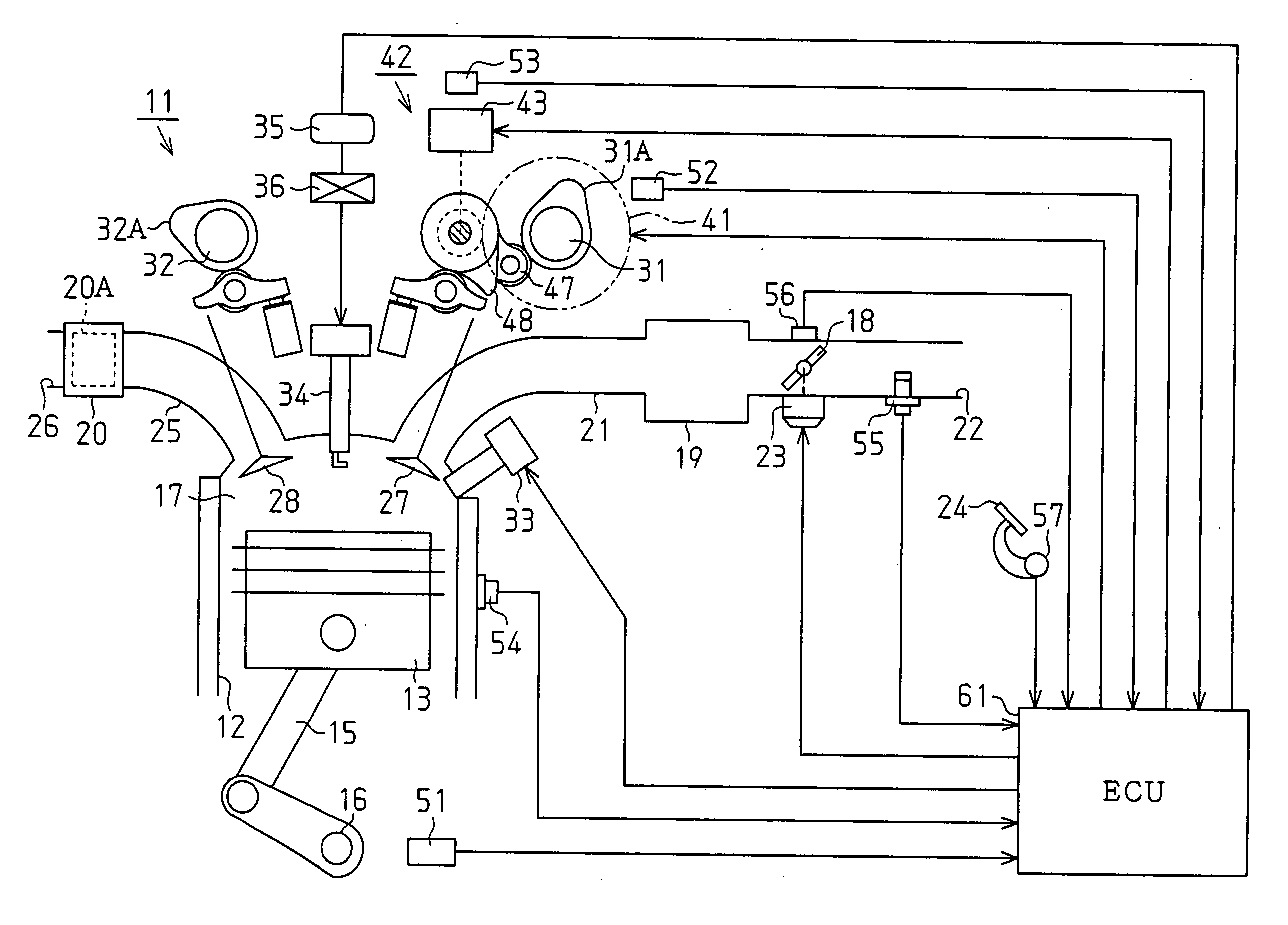
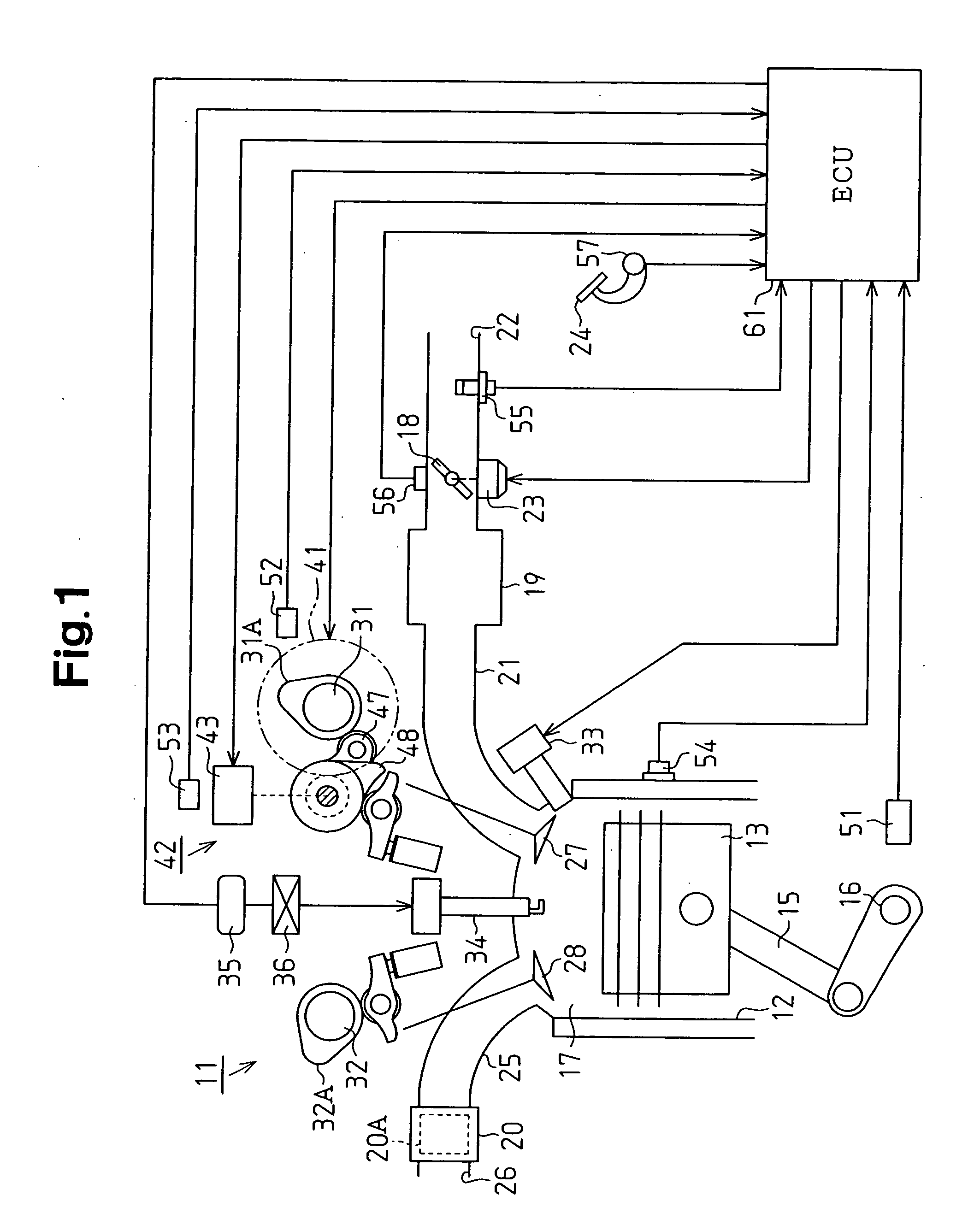
[0018] An embodiment of the present invention will now be described with reference to the drawings. As shown in FIG. 1, an in-cylinder injection gasoline engine, which functions as an internal combustion engine (referred hereafter as the “engine”) 11. The engine 11 has a plurality of cylinders 12. A piston 13 reciprocates in each cylinder 12. Each piston 13 is connected to a crankshaft 16, which functions as an output shaft of the engine 11, by a connecting rod 15. The connecting rod 15 converts the reciprocating motion of each piston 13 to rotational motion, which is then transmitted to the crankshaft 16.

[0019] Each of the cylinders 12 has a combustion chamber 17, which is connected to an intake passage 22 including a throttle valve 18, a surge tank 19, and an intake manifold 21. The ambient air of the engine 11 is drawn into the combustion chambers 17 after sequentially passing by the throttle valve 18, the surge tank 19, and the intake manifold 21 in the intake passage 22. The t...


PUM


Abstract

A valve performance controller for use in an engine that performs ignition timing retardation control to prevent knocking. The controller variably controls valve performance of an intake valve in accordance with an operation state of the engine. The controller corrects a control target so that the compression end temperature of a combustion chamber decreases when a retardation amount of the ignition timing obtained through the retardation control is greater than a predetermined value. The correction is performed only when the engine performance degradation that would occur when the ignition timing is retarded in a state in which the control target is uncorrected is predicted to be greater than the engine performance degradation that would occur when the control target is corrected.

Description

BACKGROUND OF THE INVENTION [0001] The present invention relates to an engine valve performance controller, and more particularly, to an improvement in control for preventing knocking. [0002] In recent years, various technologies have been put into practice to improve engine performance. The valve performance of engine valves (intake and exhaust valves) characteristics such as valve timing or valve lift are varied to reduce trade-off under different operational conditions (for example, refer to Japanese Patent Laid-Open Publication No. 2001-263015). [0003] Under severe operational conditions involving high temperatures and high loads, the compression end temperature within a combustion chamber becomes high. In such a state, knocking has a tendency to occur. In such a case, the ignition timing is normally retarded to decrease the combustion speed and thus prevent knocking. [0004] However, if the combustion speed is decreased by retarding the ignition timing, the exhaust gas temperatu...

Claims


Application Information

Patent Timeline
Patent Type & Authority Applications(United States)
IPC IPC(8): F01L1/34
CPCF01L1/34Y02T10/18F01L13/0031F01L2001/186F02B23/104F02B2075/125F02D13/023F02D13/0238F02D13/0261F02D35/027F02D37/02F02D2041/001F02P5/152Y02T10/46F01L13/0015Y02T10/12Y02T10/40
Inventor MIYANOO, YUJITAKIMOTO, FUMITO
Owner TOYOTA JIDOSHA KK
Why Eureka
Try Eureka