Apparatus and method for filling fuel

Inactive Publication Date: 2006-01-26
TAIYO NIPPON SANSO CORP
View PDF7 Cites 39 Cited by
  • Summary
  • Abstract
  • Description
  • Claims
  • Application Information

AI Technical Summary

Benefits of technology

[0030] According to the foregoing description, an object of the present invention is to provide a fuel filling apparatus with an overfilling protective valve, in whi

Problems solved by technology

As a result, there will be a problem that the overfilling protective valve 120 fails to operate by the correct set pressure.
Therefore, when the nature gas is filled into the fuel tank, since the gas temperature is very difficult to rise, the gas can be easily filled within a short time without managing the tank temperature.
Since the fuel tank made of FRP has an upper limit for the temperature, a serious temperature management is required during filling the hydrogen gas.
Additionally, it is very difficult to increase the filling speed.
However, in the above method,

Method used


Image

  • Apparatus and method for filling fuel
  • Apparatus and method for filling fuel
  • Apparatus and method for filling fuel

Examples


first embodiment

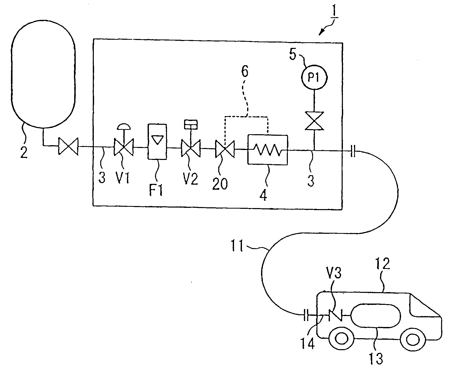
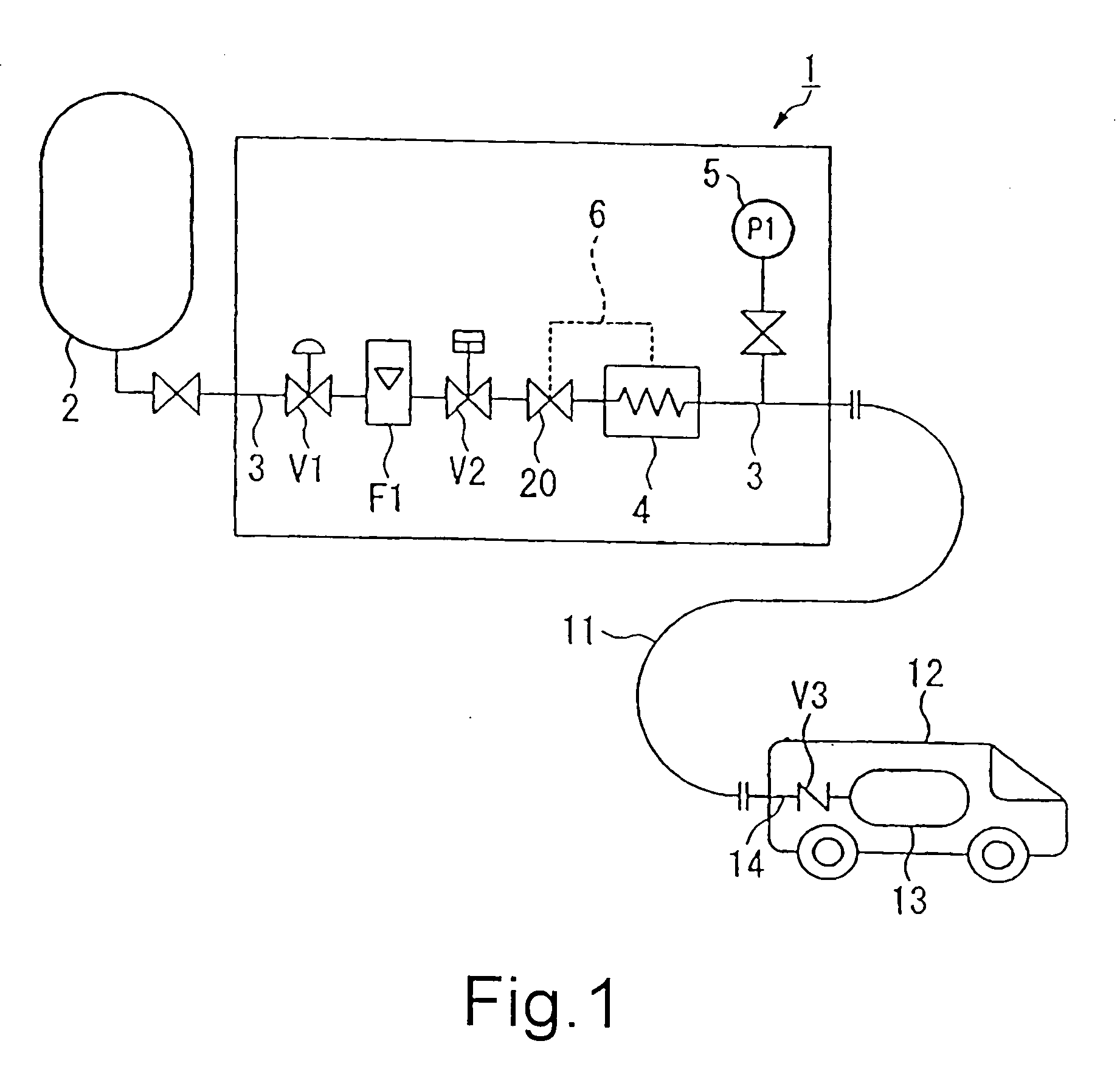
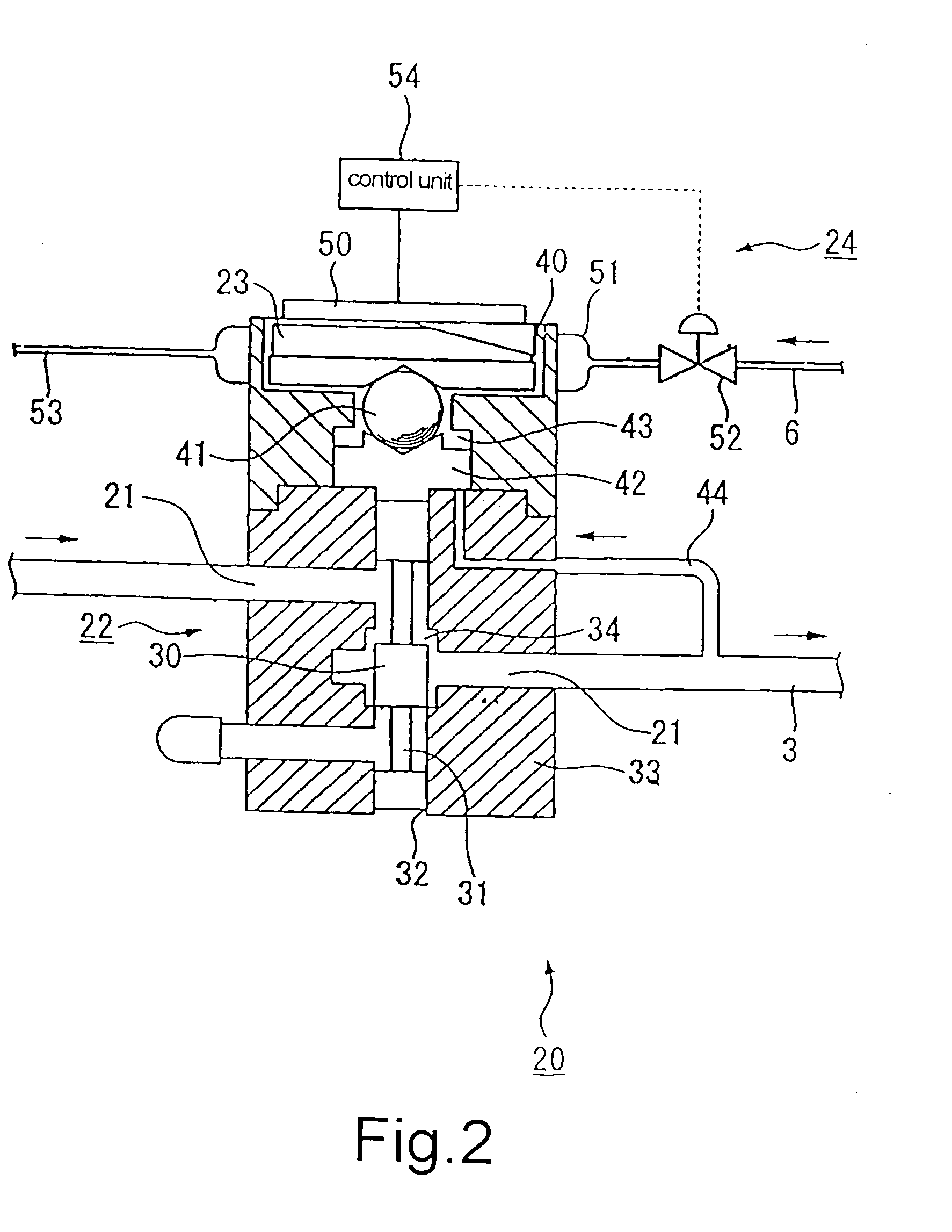
[0063]FIG. 1 schematically shows a structure of a fuel filling apparatus according to the first embodiment of the present invention. FIG. 2 is a cross-sectional view of an exemplary overfilling protective valve that is applicable to the fuel filling apparatus shown in FIG. 1.

[0064] As shown in FIG. 1, the fuel filling apparatus 1 comprises a fuel gas supply path 3, a flow modulating valve V1, an integrating flowmeter F1, a shut-off valve V2, an overfilling protective valve 20, a heat exchanger 4 and a pressure gauge 5. The fuel gas supply path 3 is used for supplying the fuel gas from a reservoir tank 2. The flow modulating valve V1 modulates a supply amount of the fuel gas. The integrating flowmeter F1 measures and integrates a flow of the fuel gas. The shut-off valve V2 closes the fuel gas supply path 3 when filling the fuel gas is finished. The overfilling protective valve 20 will close the supply path 3 when the shut-off valve V2 malfunctions. The heat exchanger 4 is used to co...

second embodiment

[0087]FIG. 3 schematically shows a structure of a fuel filling apparatus according to the second embodiment of the present invention. FIG. 4 is a cross-sectional view of an exemplary overfilling protective valve that is applicable to the fuel filling apparatus shown in FIG. 3. The second embodiment is suitable for the compressed nature gas whose temperature will decrease due to the Joule Thomson effect.

[0088] The fuel filling apparatus 60 in FIG. 3 basically has the same structure as the fuel filling apparatus in FIG. 1, except for no heat exchanger 4 and the structure of the overfilling protective valve 61 in FIG. 4.

[0089] The overfilling protective valve 61 comprises a fuel gas passage 21, a valve unit 22 for opening or closing the fuel gas supply passage 21 by a valve body 30, a valve body displacement means 23 for displacing the valve body 30 based on a filled pressure of the fuel gas, and a temperature modulating unit 62 for modulating the temperature of the spring 23.

[0090]...

third embodiment

[0097]FIG. 5 shows another structure of the fuel filling apparatus according to the third embodiment of the present invention.

[0098] In FIG. 5, the fuel filling apparatus 1 has a casing 206 in which a hydrogen gas supply path 3, a flow modulating valve V1, an integrating flowmeter F1, a heat exchanger 4, a shut-off valve V2 and a pressure gauge5 are arranged. The fuel gas supply path 3 is used for supplying the hydrogen gas from a hydrogen gas reservoir tank 2. The flow modulating valve V1 modulates a supply amount of the hydrogen gas. The integrating flowmeter F1 measures and integrates a flow of the hydrogen gas. The shut-off valve V2 is arranged in the hydrogen gas supply path 3. The heat exchanger 4 is used to cool the hydrogen gas, and the pressure gauge 5 is used to detect a pressure of the hydrogen gas that is filled into the automobile.

[0099] The casing 206 is made of a rigid material such as metal (e.g., stainless, etc.) or plastic (e.g., acryl resin, etc.). The casing is...


PUM

PropertyMeasurementUnit
Temperatureaaaaaaaaaa
Pressureaaaaaaaaaa

Abstract

A fuel filling apparatus is provided. The fuel filling apparatus comprises an overfilling protective valve arranged in a fuel gas supply path for supplying a fuel gas to an automobile. The overfilling protective valve further comprises a fuel gas path, a valve unit for opening and closing the fuel gas path by a valve body, a valve body displacement means for displacing the valve body according to a filling pressure of the fuel gas, and a temperature modulating unit for modulating a temperature of the valve body displacement means. Even though a difference between the temperature of the fuel gas and the operation temperature of the overfilling protective valve is large, the temperature of the valve body displacement means can be maintained within the preset temperature range by the temperature modulating unit and the overfilling protective valve can be exactly operated under the preset pressure.

Description

BACKGROUND OF THE INVENTION [0001] 1. Field of the Invention [0002] This invention relates in general to an apparatus and a method for filling fuel. Hydrogen gas or compressed nature gas is filled as a fuel gas into an automobile. [0003] 2. Description of the Related Art [0004] As a next generation automobile, compressed nature gas automobiles using compressed nature gas as the fuel gas and hydrogen gas automobiles using hydrogen gas as the fuel gas are developed. These automobiles are characterized in that discharge amount of carbon dioxide gas, nitrogen oxide (NOx), and oxysulfide (SOx), etc. is very little. [0005] For refueling, these automobiles are the same as the gasoline automobile. These automobiles arrive at a supply base having a fuel filling apparatus (dispenser) for filling their fuel, i.e., the compressed nature gas or the hydrogen gas, and the compressed nature gas or the hydrogen gas are supplied from the fuel filling apparatus (for example, referring to non-patent do...

Claims


Application Information

Patent Timeline
IPC IPC(8): B65B3/22F17C5/00F17C13/02
CPCF17C5/007F17C5/06F17C13/026F17C2221/012F17C2227/0341F17C2227/0355Y02E60/321F17C2227/0388F17C2250/0439F17C2250/0631F17C2250/0636F17C2270/0139F17C2227/0365Y02E60/32Y02P90/45F17C5/00F17C13/02
Inventor TAKANO, NAOYUKISATO, KAZUTOSHIOMORI, KANJI
Owner TAIYO NIPPON SANSO CORP
Why Eureka
Try Eureka