Illumination optical system, illumination apparatus using the illumination optical system, and observation system provided with the illumination optical system or the illumination apparatus

a technology of illumination optical system and illumination optical system, which is applied in the direction of instruments, lighting and heating apparatus, fibre light guides, etc., can solve the problems of difficult to broaden the light distribution area to such an extent, the distribution angle exceeds 120°, and the loss is generated in the quantity of ligh

Active Publication Date: 2006-01-26
OLYMPUS CORP
View PDF5 Cites 31 Cited by
  • Summary
  • Abstract
  • Description
  • Claims
  • Application Information

AI Technical Summary

Problems solved by technology

In the illumination optical system constructed using a negative lens, to secure a broad area on which illumination light is distributed with the negative lens, a loss is generated in the quantity of light, unless the outer diameter of the negative lens is increased.
Therefore, for example, in an illumination optical system using a negative lens, it is difficult to broaden the light distribution area to such an extent that the light distribution angle exceeds 120°.
When the light distribution area is broadened, the radius of curvature of the concave surface of the negative lens is reduced, and it becomes difficult to work the lens.
It is difficult to realize an illumination optical system having light distribution characteristics such that the light distribution exceeds 150° when using a positive lens.
Moreover, when a light guide fiber bundle is used as a light source of the illumination optical system, there is a problem that light distribution unevenness is generated.
Furthermore, since the light is separated into colors by dispersion of the glass material of the lens included in the illumination optical system, there is a problem that color unevenness is generated in the peripheral portion of the illuminated area.
The color unevenness is generated in the case where the illu...

Method used


Image

  • Illumination optical system, illumination apparatus using the illumination optical system, and observation system provided with the illumination optical system or the illumination apparatus
  • Illumination optical system, illumination apparatus using the illumination optical system, and observation system provided with the illumination optical system or the illumination apparatus
  • Illumination optical system, illumination apparatus using the illumination optical system, and observation system provided with the illumination optical system or the illumination apparatus

Examples


embodiment 1

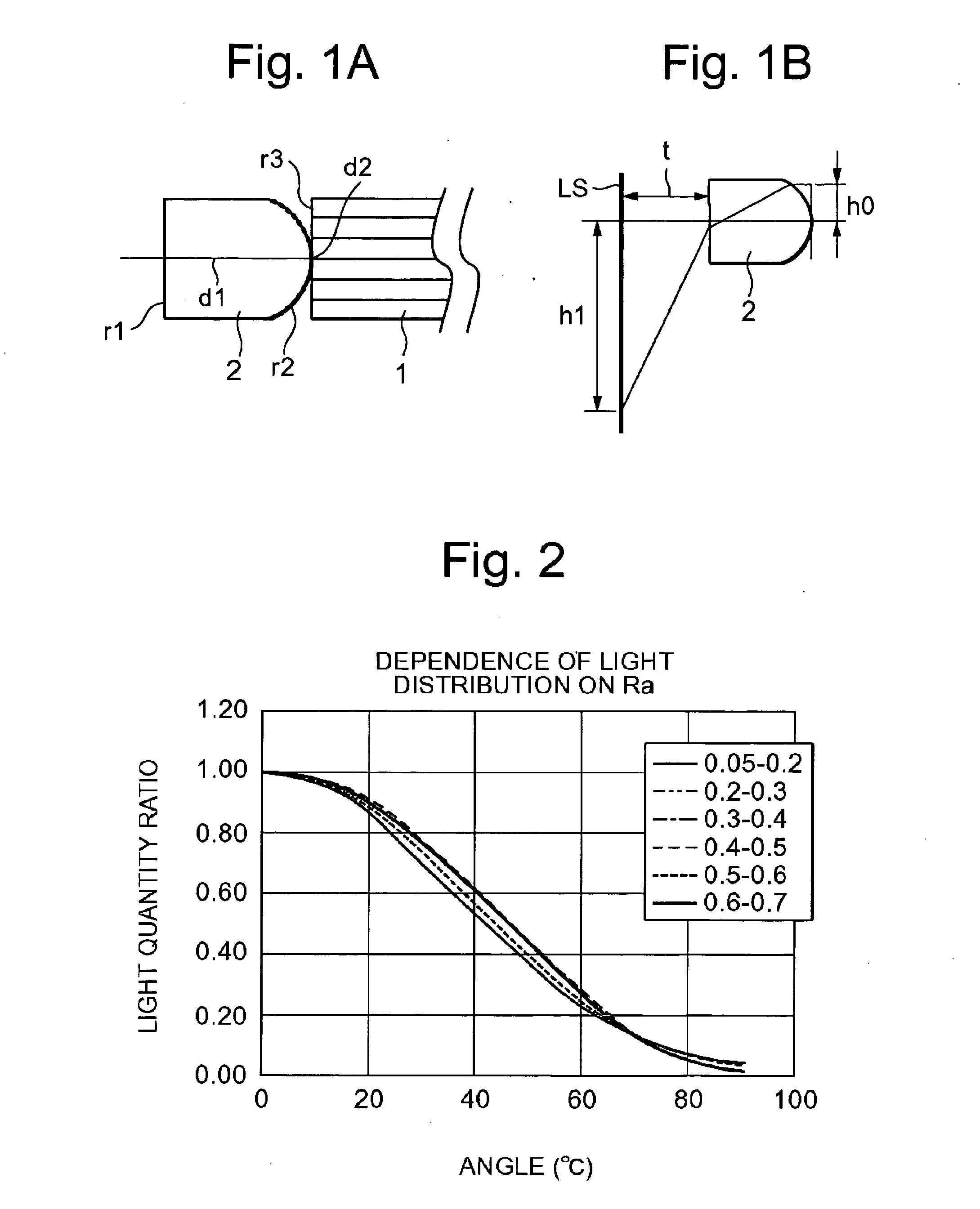
[0121]FIG. 1 shows diagrams of Embodiment 1 of an illumination optical system. FIG. 1A is a sectional view along an optical axis, and FIG. 1B is an explanatory view showing that illumination light parallel to the optical axis is projected via the illumination optical system.

[0122] The illumination optical system 2 of Embodiment 1 comprises a piano-convex lens having a flat surface on the object side and a convex surface on the light guide fiber bundle side. The convex surface r2 of the plano-convex lens is an aspherical surface, and the aspherical surface is roughened. This roughened surface prevents generation of light distribution unevenness and color unevenness. The plano-convex lens is disposed in such a manner that the convex surface r2 is brought into contact with an emission end surface r3 of the light guide fiber bundle 1. The arithmetic average roughness Ra of the roughened surface is about 0.3 μm. The arithmetic average roughness Ra may be in a range of 0.05 to 0.75 μm.

[...

embodiment 2

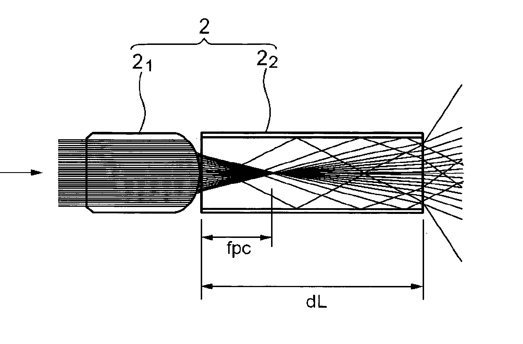
[0151]FIGS. 12A and 12B are diagrams showing Embodiment 2 of the illumination optical system. FIG. 12A is a sectional view along an optical axis, and FIG. 12B is an explanatory view showing that illumination light parallel to the optical axis is projected via the illumination optical system.

[0152] The illumination optical system 2 of Embodiment 2 comprises: a plano-convex lens 21 having a flat surface on its object side and a convex surface on the light guide fiber bundle side; and a single fiber 22. An incidence end surface r4 of the single fiber 22 is brought into contact with an emission end surface r5 of a light guide fiber bundle 1, and an emission end surface r3 of the single fiber 22 is brought into contact with a convex surface r2 of the plano-convex lens 21. The convex surface r2 of the plano-convex lens 21 is formed as an aspherical surface, and the aspherical surface is roughened. The arithmetic average roughness Ra of the roughened surface is about 0.2 μm. In Embodiment...

embodiment 3

[0184]FIGS. 14A and 14B are diagrams showing Embodiment 3 of the illumination optical system. FIG. 14A is a sectional view along the optical axis, and FIG. 14B is an explanatory view showing that illumination light parallel to the optical axis is projected via the illumination optical system.

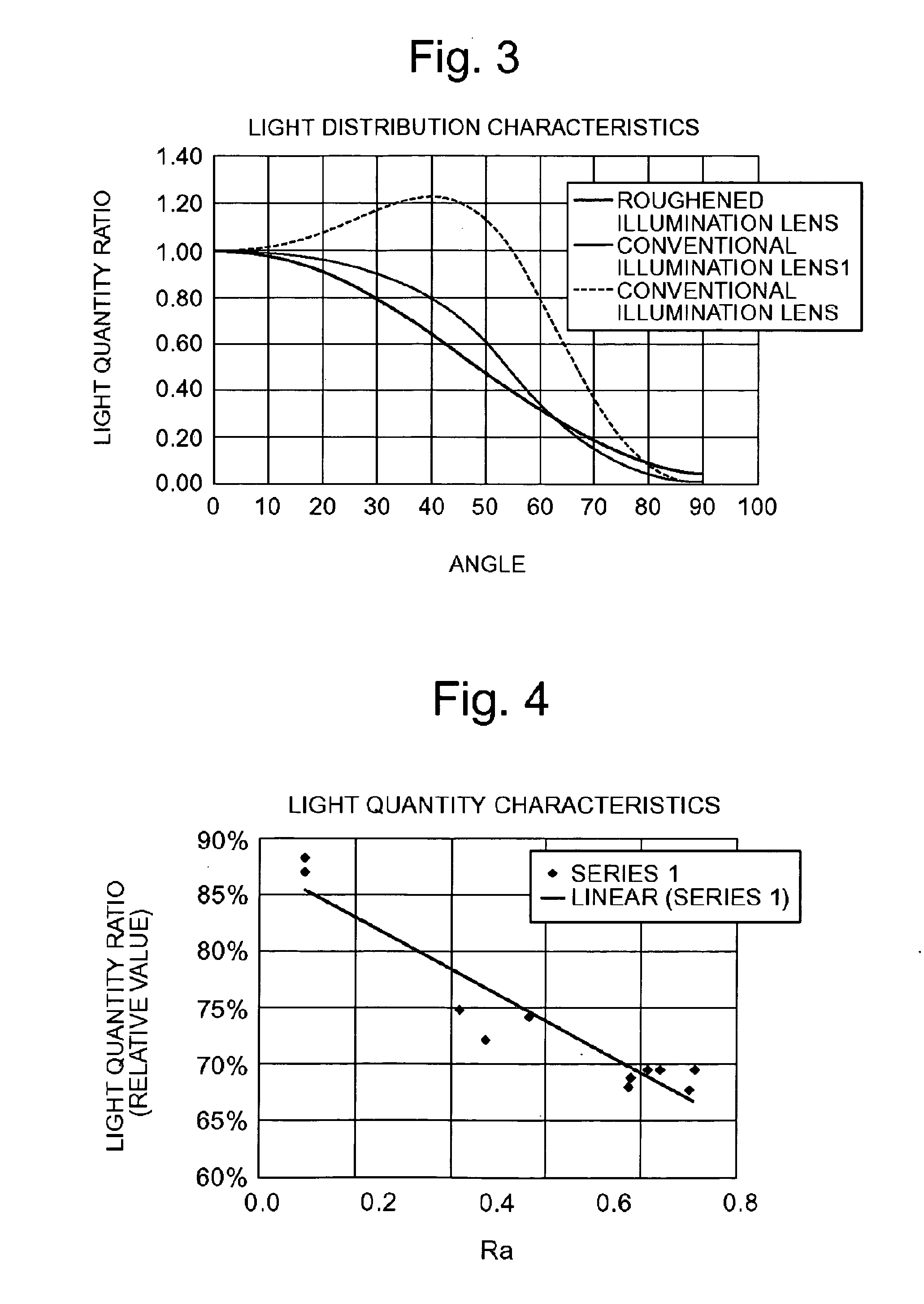
[0185] An illumination optical system 2 of Embodiment 3 comprises: a plano-convex lens 21a having a flat surface on an object side and a convex surface on a light guide fiber bundle side; and a double-convex lens 21b. A convex surface r2 of the plano-convex lens 21a is formed into a spherical shape, and the spherical surface is roughened. In the illumination optical system 2 of Embodiment 3, the lens surface having a small radius of curvature and an intense light refracting action is roughened. Therefore, diffusing effects are easily produced, and light distribution is easily broadened. Light distribution unevenness is suppressed by the roughened surface. Moreover, since the surface disposed ne...


PUM


Abstract

An illumination optical system disposed in order to diffuse illumination light emitted from a light source, includes at least one optical device having a roughened optical surface, with the arithmetic average roughness of the roughened surface set in a range of 0.05 to 0.75 [μm].

Description

CROSS REFERENCE TO RELATED APPLICATION [0001] This application claims benefit under 35 U.S.C. §119 of Japanese Patent Application No. 2004-216,035, filed in Japan on Jul. 23, 2004, the contents of which are incorporated by reference. BACKGROUND OF THE INVENTION [0002] 1. Field of the Invention [0003] The present invention relates to an illumination optical system, an illumination apparatus using this system, and an observation system using the illumination apparatus. [0004] 2. Description of the Related Art [0005] As an illumination optical system for illuminating a broad area of an object, there is a system in which a light emitting device such as a lamp or an LED, or an end surface of a light guide fiber bundle that transmits light is used as a light source, and light emitted from the light source is diverged by a negative lens or a positive lens. [0006] In the illumination optical system constructed using a negative lens, to secure a broad area on which illumination light is dist...

Claims


Application Information

Patent Timeline
IPC IPC(8): G02B21/02
CPCG02B6/0006G02B23/26G02B23/2469G02B6/06
Inventor TAKASUGI, YOSHIHARU
Owner OLYMPUS CORP
Why Eureka
Try Eureka