Illuminator and production method

a technology of illuminator and production method, which is applied in the direction of lighting and heating apparatus, printed circuit aspects, lighting heating/cooling arrangements, etc., can solve the problems of not being able to achieve high led densities, thermal resistance of packages, and limiting the densities which can be achieved by packs or surface mount packages

Inactive Publication Date: 2006-01-26
STOCKERYALE IRL
View PDF3 Cites 38 Cited by
  • Summary
  • Abstract
  • Description
  • Claims
  • Application Information

AI Technical Summary

Problems solved by technology

The thermal resistance of the package is acceptable for some applications, but limited by the length of the pins connecting it to the rest of the assembly.
These typically work well, but are not capable of achieving high LED densities.
However, the physical dimensions of T-Packs or surface mount packages limit the de...

Method used


Image

  • Illuminator and production method
  • Illuminator and production method
  • Illuminator and production method

Examples


Embodiment Construction

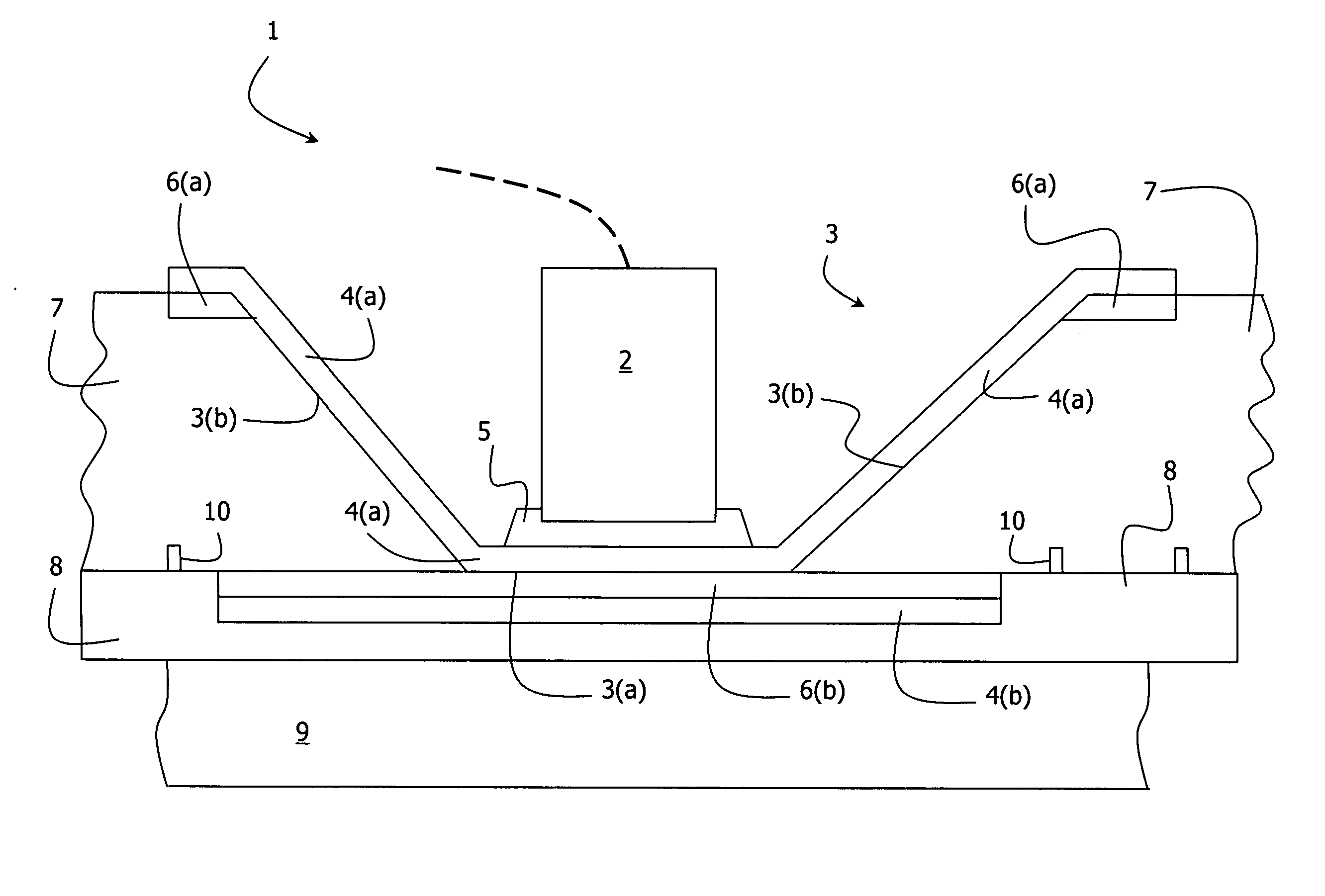
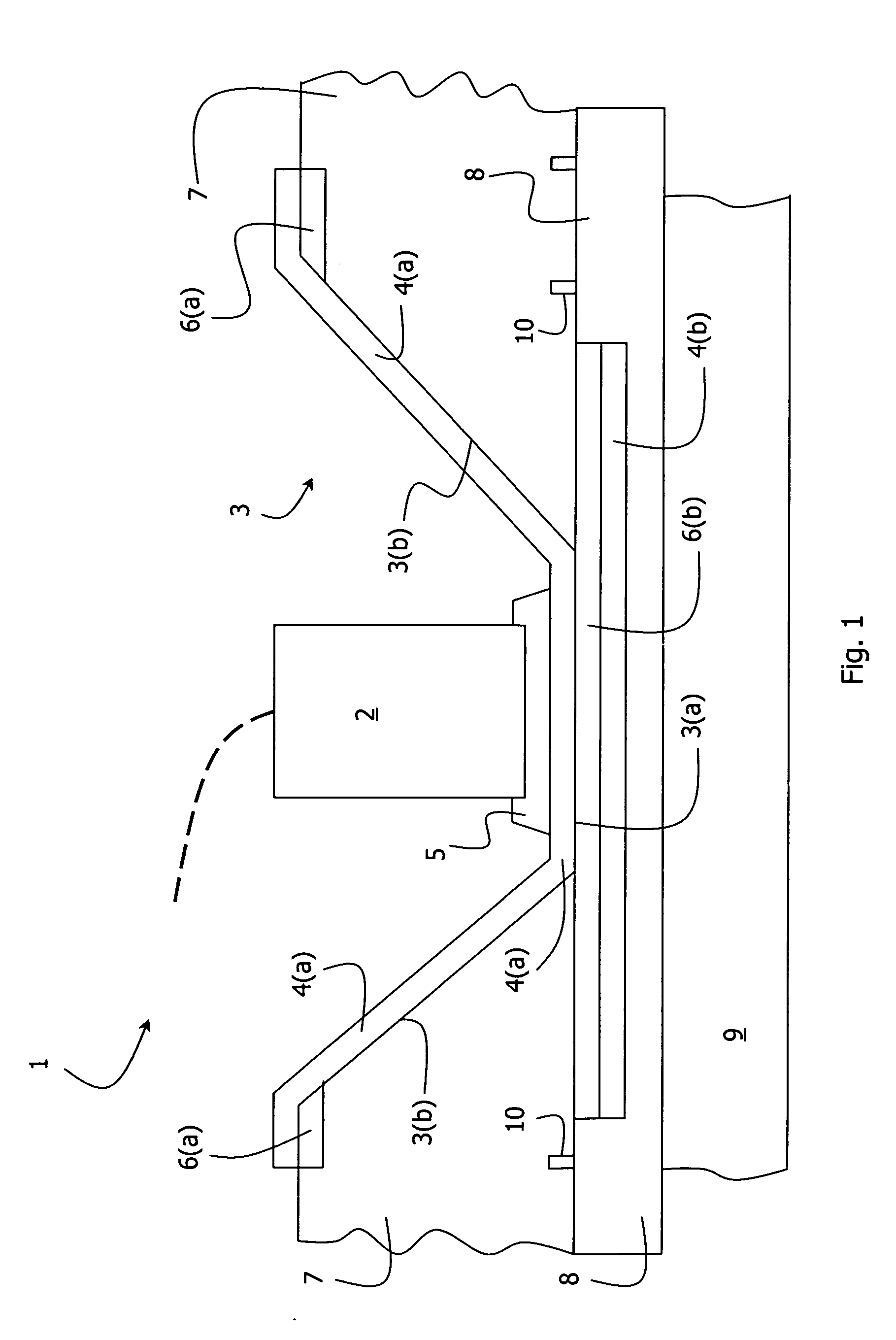
[0045] The invention provides an illuminator comprising an array of bare die LEDs with a close packing density, good thermal diffusion, and high optical efficiency. The illuminator is manufactured using conventional circuit board manufacturing techniques and materials and so excellent manufacturing efficiency can be achieved. One light unit 1 of the illuminator is shown in FIG. 1, the others being similar and being manufactured simultaneously.

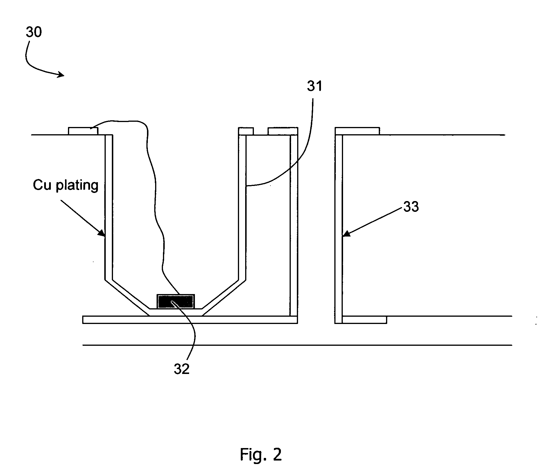
[0046] An LED 2 is mounted in a cavity 3 having a round shape in plan, a flat circular base 3(a) and a tapered side wall 3(b). The cavity 3 is formed in an FR4 substrate 7 and is coated with a reflective coating 4(a). The reflective coating is also a conductor forming part of the drive circuit of the illuminator. The LED 2 is secured to the cavity base 3(a) by conductive adhesive 5. The reflective coating 4(a) extends over the Cu conductor plating 6(a) around the rim of the cavities 3.

[0047] The substrate 7 is an FR4 printed circuit board hav...


PUM


Abstract

An illuminator (1) has an array of cavities (3) are drilled in a substrate having an FR4 electrically insulating body (7) plated with copper conductors (6(a), 6(b)). Further patterning of the substrate provided electrical conductors (3(b)) in the cavities to act as both part of the light drive circuit and reflectors in the cavities. The drilling is performed to the full depth of the FR4 body (7) until underneath plating (6(b)) is reached. A further Cu plating (4(b)) is applied on the platings (6(b)) so that they together form a heat spreader under each cavity (3). A layer (8) of resin incorporating thermally conductive particles is bonded to the underside surfaces, both of the FR4 (7) and of the platings (4(b)). A heat sink (9) is bonded to the layer (8). Good optical efficiency and thermal dissipation is achieved, despite the fact that conventional PCT processing techniques are used.

Description

INTRODUCTION [0001] 1. Field of the Invention [0002] The invention relates to an illuminator and to a method for producing an illuminator. [0003] 2. Prior Art Discussion [0004] Light emitting and infrared emitting diodes (referred to hereinafter as “LEDs” are widely used as indicators and as sources of illumination for a wide variety of applications. In order to ensure maximum efficiency, reliable operation, and a long lifetime it is necessary to take various measures in assembling the LEDs into packages or into housings such as are typically used in illuminators. [0005] For the use of single or small numbers of LED dies, the through-pin package (“T-Pack”) has been developed. In this package the die sits in a metal reflective cavity which enables good optical efficiency by reflecting light from the sides of the chip towards a moulded lens intrinsic to the package. The thermal resistance of the package is acceptable for some applications, but limited by the length of the pins connect...

Claims


Application Information

Patent Timeline
IPC IPC(8): F21V7/00H01L27/15H01L33/62H05K1/02H05K1/18
CPCH01L33/62H05K1/021H05K1/183H05K2201/0394H01L2224/73265H05K2201/09981H05K2201/10106H05K2203/049H01L2224/32225H05K2201/09509
Inventor LINEHAN, DANIELBJORSELL, STENSTANLEY, SIMONKELLY, WILLIAM
Owner STOCKERYALE IRL
Why Eureka
Try Eureka