Gas supplying system and gas supplying method

a gas supply system and gas supply technology, applied in fluid pressure control, process and machine control, instruments, etc., can solve the problems of short startup and shutdown time, big performance drop,

a gas supply system and gas supply technology, applied in fluid pressure control, process and machine control, instruments, etc., can solve the problems of short startup and shutdown time, big performance drop,

US20060019134A1Inactive Publication Date: 2006-01-26MITSUBISHI HEAVY IND LTD

Image

  • Gas supplying system and gas supplying method
  • Gas supplying system and gas supplying method
  • Gas supplying system and gas supplying method

Examples


Embodiment Construction

[0086] The embodiments of a gas supplying system, an energy supplying system and a gas supplying method of the present invention will be described below with reference to the attached drawings. In this embodiment, the explanation about oxidizing agent gas (for example, oxygen gas or air) supplied to a fuel cell system is omitted.

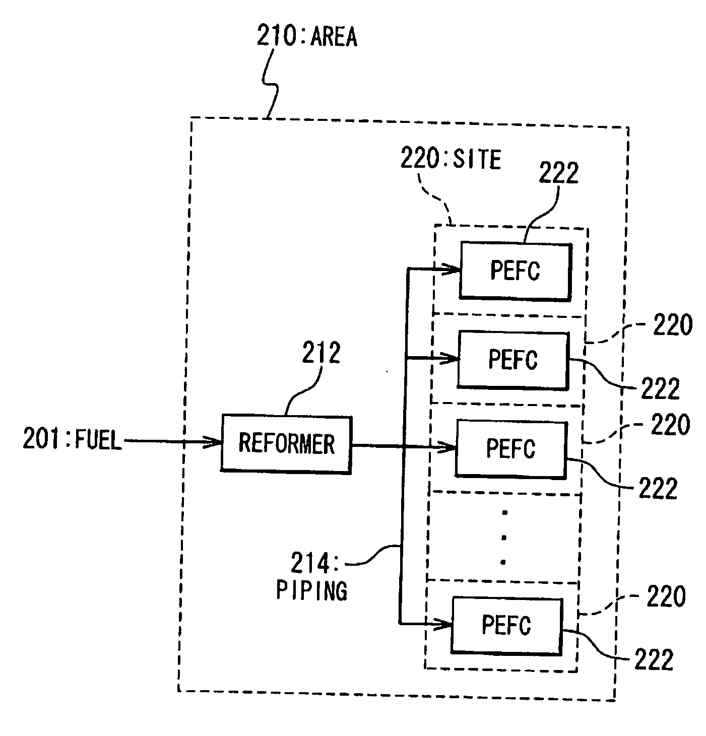
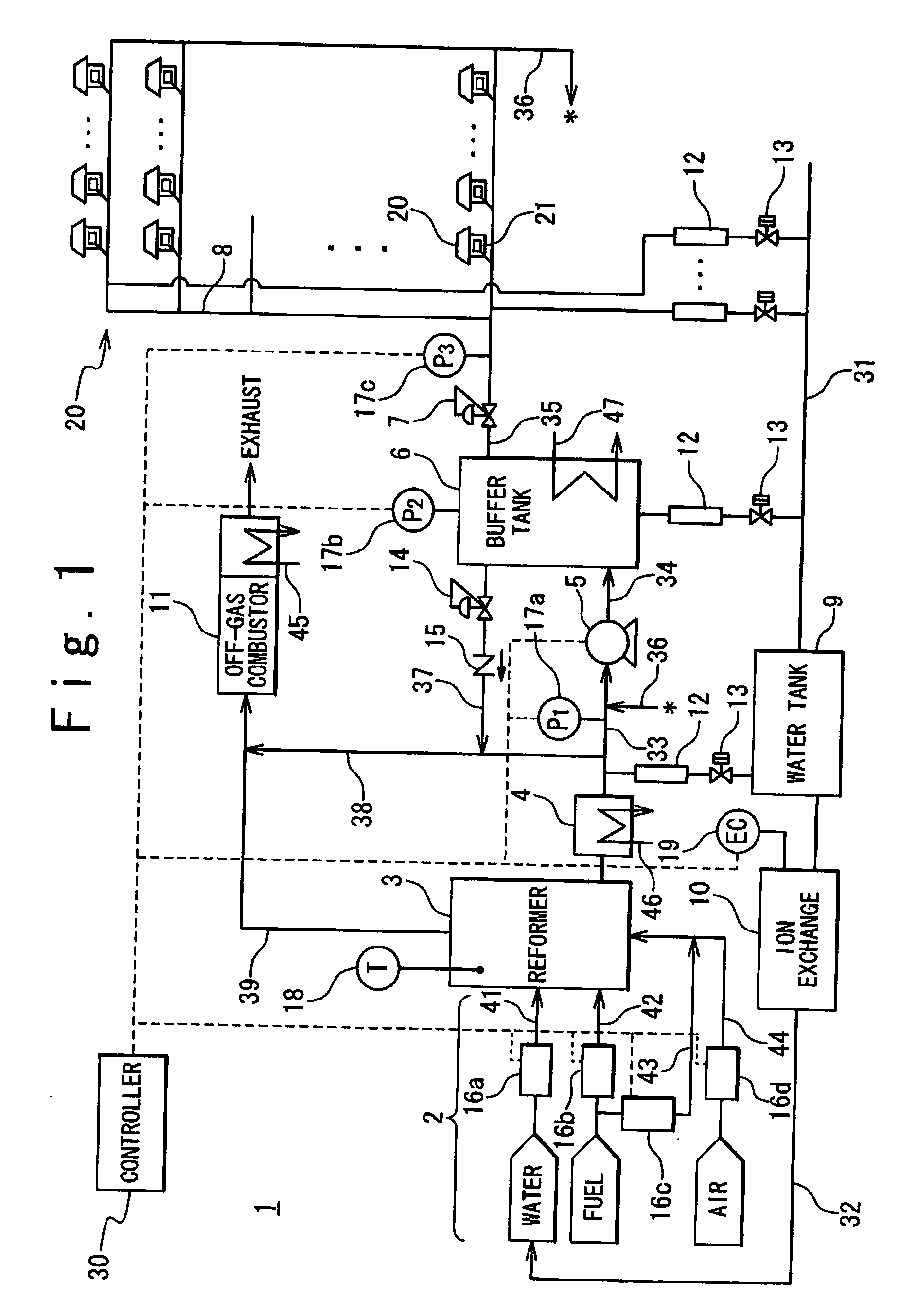
[0087] At first, the configuration of the energy supplying system to which the gas supplying system of the embodiment of the present invention is applied is explained with reference to the attached drawings. FIG. 1 is a block diagram showing the configuration of the embodiment of the energy supplying system of the present invention. The energy supplying system includes a plurality of fuel cell systems 21 and a gas supplying system 1.

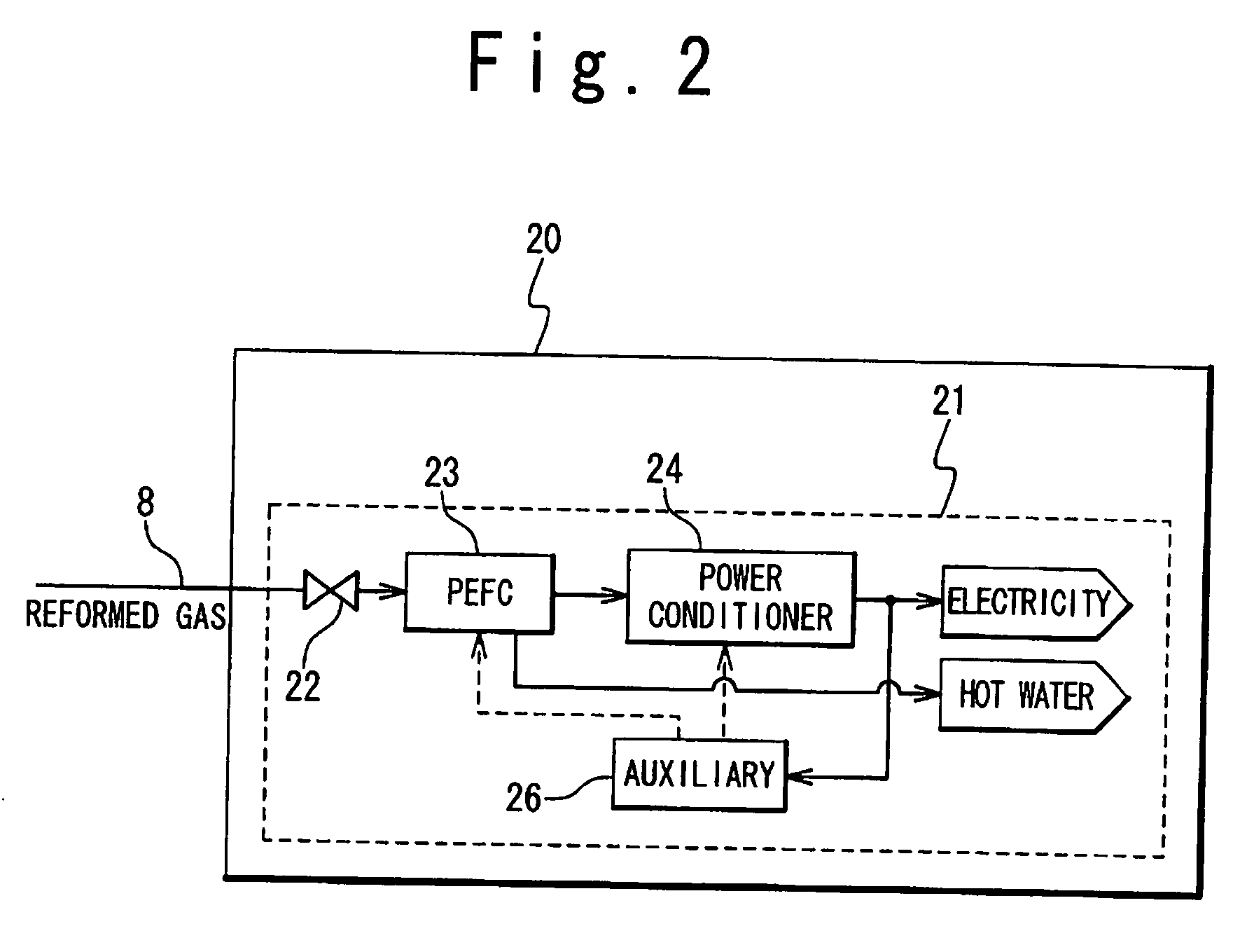
[0088] Each of the plurality of fuel cell systems 21 receives the supply of reformed gas as fuel gas from the gas supplying system 1 and generates the electric power and heat (water of a high temperature) which are mainly used ...


PUM


Abstract

A gas supplying system for fuel cell includes a reformer generating a reformed gas by reforming a mixed raw material including a fuel and a first water, a piping network distributing the reformed gas to fuel cell systems each of which is installed in different rooms or buildings, a drain recovery unit recovering a water condensed from the reformed gas in the piping network. The piping network has a circulating route. By the circulation route, the reformed gas does not stay in the piping network so that the water condensation in the piping is suppressed. The water in the piping is removed by the drain recovery unit. According to this configuration, the clogging and corrosion of the piping caused by the condensed water is avoided.

Description

BACKGROUND OF THE INVENTION [0001] 1. Field of the Invention [0002] The present invention relates to a gas supplying system and a gas supplying method, and more particularly relates to a gas supplying system and a gas supplying method which supply a reformed gas. [0003] 2. Description of the Related Art [0004] Conventionally, a technique which uses a fuel cell as a distributed power source is known. For example, a cogeneration system is considered which uses a polymer electrolyte fuel cell (PEFC) and is jointly installed in a building, such as a typical house, a condominium and a building. In such a cogeneration, a case may be considered in which each of a plurality of PEFCs is distributed and placed for each house, room and floor. In this case, it is required that the individual PEFC is minimized and does not take a large space. To fulfill such requirements, integration of the sharable facilities in the plurality of PEFCs is an effective method. [0005] As the sharable facility, a r...

Claims


Application Information

Patent Timeline
26 Jan 2006
Publication
US20060019134A1
IPC
H01M8/06; H01M8/04
CPC
C01B3/384; Y02E60/50; C01B3/505; C01B3/56; C01B2203/0283; C01B2203/042; C01B2203/044; C01B2203/066
Inventors
YAGI, KATSUKI; NOJIMA, SHIGERU