

Apparatus and method for automated protein design
a protein design and protein technology, applied in the field of automatic protein design, can solve the problems of hampered development of improved, second generation, proteins, and many designed proteins lacking the structural specificity of native proteins
- Summary
- Abstract
- Description
- Claims
- Application Information
AI Technical Summary
Benefits of technology
Problems solved by technology
Method used
Image

Examples
example 1
Protein Design Using van der Waals and Atomic Solvation Scoring Functions with DEE
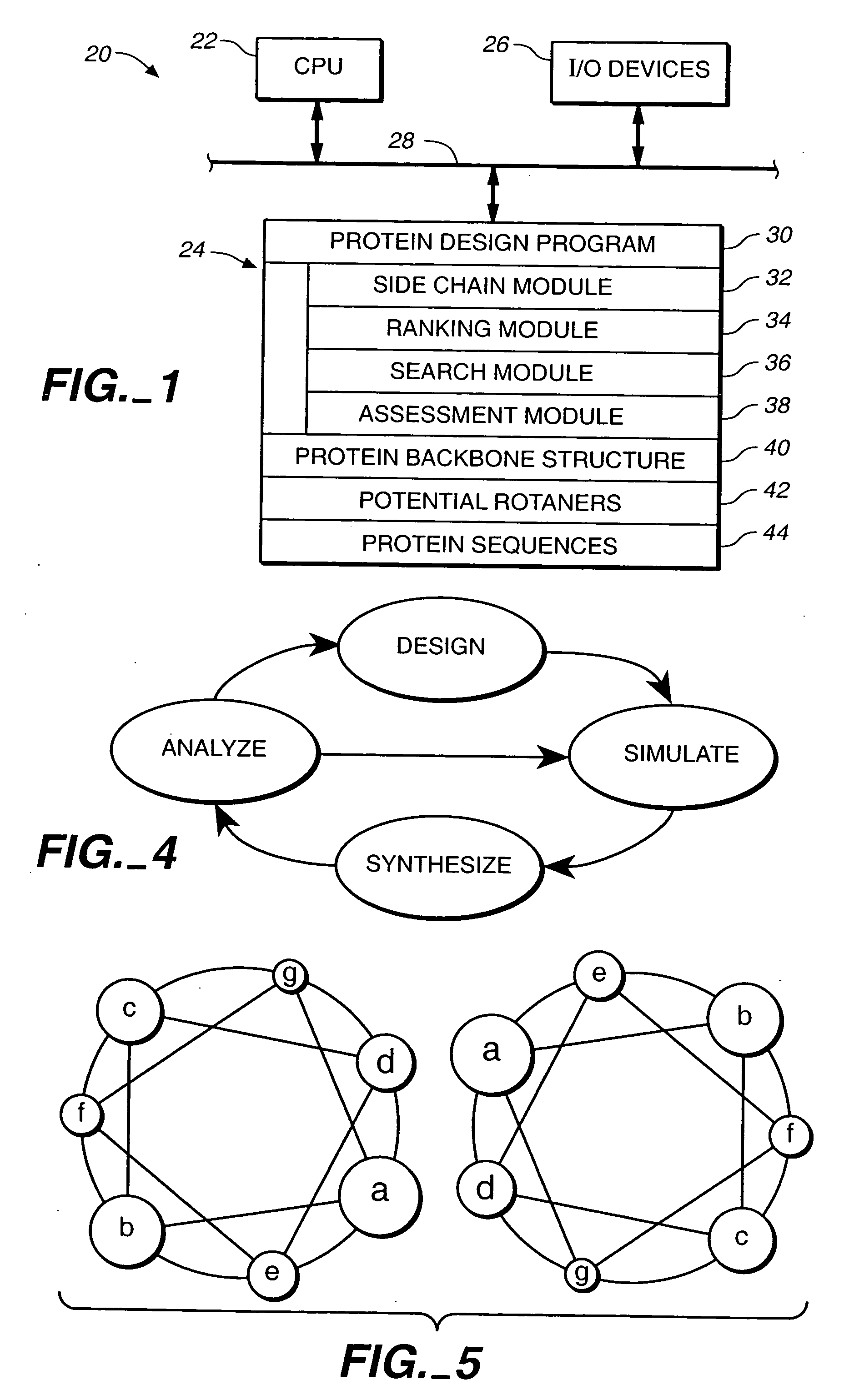
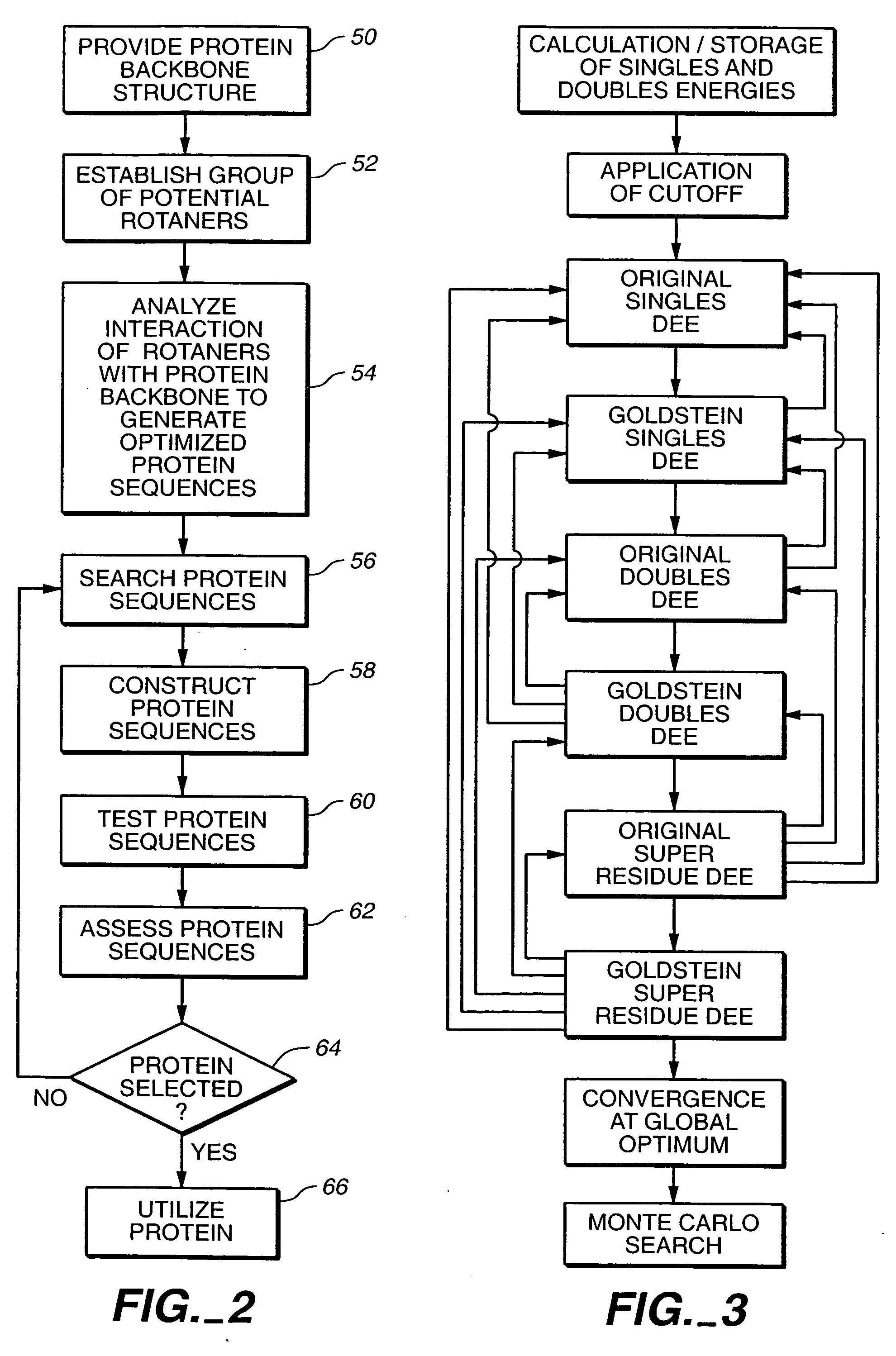
[0178] A cyclical design strategy was developed that couples theory, computation and experimental testing in order to address the problems of specificity and learning (FIG. 4). Our protein design automation (PDA) cycle is comprised of four components: a design paradigm, a simulation module, experimental testing and data analysis. The design paradigm is based on the concept of inverse folding (Pabo, Nature 301:200 (1983); Bowie, et al., Science 253:164-170 (1991)) and consists of the use of a fixed backbone onto which a sequence of side-chain rotamers can be placed, where rotamers are the allowed conformations of amino acid side chains (Ponder, et al., (1987) (supra)). Specific tertiary interactions based on the three dimensional juxtaposition of atoms are used to determine the sequences that will potentially best adopt the target fold. Given a backbone geometry and the possible rotamers allowed for ea...
example 2
Automated Design of the Surface Positions of Protein Helices
[0207] GCN4-p1, a homodimeric coiled coil, was again selected as the model system because it can be readily synthesized by solid phase techniques and its helical secondary structure and dimeric tertiary organization ease characterization. The sequences of homodimeric coiled coils display a seven residue periodic hydrophobic and polar pattern called a heptad repeat, (a•b•c•d•e•f•g) (Cohen & Parry, supra). The a and d positions are buried at the dimer interface and are usually hydrophobic, whereas the b, c, e, f, and g positions are solvent exposed and usually polar (FIG. 5). Examination of the crystal structure of GCN4-p1 (O'Shea, et al., supra) shows that the b, c, and f side chains extend into solvent and expose at least 55% of their surface area. In contrast, the e and g residues bury from 50 to 90% of their surface area by packing against the a and d residues of the opposing helix. We selected the 12 b, c, and f residue...
example 3
Design of a Protein Containing Core, Surface and Boundary Residues Using van der Waals, H-Bonding, Secondary Structure and Solvation Scoring Functions
[0222] In this example, core, boundary and surface residue work was combined. In selecting a motif to test the integration of our design methodologies, we sought a protein fold that would be small enough to be both computationally and experimentally tractable, yet large enough to form an independently folded structure in the absence of disulfide bonds or metal binding sites. We chose the ββα motif typified by the zinc finger DNA binding module (Pavletich, et al. (1991) (supra)). Though it consists of less than 30 residues, this motif contains sheet, helix, and turn structures. Further, recent work by Imperiali and coworkers who designed a 23 residue peptide, containing an unusual amino acid (D-proline) and a non-natural amino acid (3-(1,10-phenanthrol-2-yl)-L-alanine), that takes this structure has demonstrated the ability of this fol...
PUM
 Abstract
Description
Claims
Application Information