Adaptive correction of a received signal frequency response tilt

a technology of received signal and frequency response, applied in the field of adaptive correction of received signal frequency response tilt, can solve problems such as observed leakage energy, and achieve the effects of minimizing leakage, minimizing distortion in received modulated signal, and minimizing measurement distortion

Inactive Publication Date: 2006-01-26
CIENA
View PDF2 Cites 14 Cited by
  • Summary
  • Abstract
  • Description
  • Claims
  • Application Information

AI Technical Summary

Benefits of technology

[0004] In accordance with the present invention, a receiver has apparatus for adaptively minimizing distortion in a received modulated signal. The apparatus includes a leakage sensor for measuring leakage and an equalizer controller for modifying the frequency response based on the measured leakage. The leakage sensor provides a frequency response error based on leakage measured on a leakage signal orthogonal to the received modulated signal. The receiver also includes an equalizer having a frequency response. The frequency response is selected to minimize distortion in the received modulated signal. The equalizer controller coupled to the leakage sensor and the equalizer adjusts the frequency response of the equalizer in the receiver dependent on the frequency response error to minimize the measured leakage.
[0005] The frequency response error is a difference between currently measured leakage and previously measured leakage. The leakage sensor also includes a decision circuit. The decision circuit modifies the frequency response error provided by the leakage sensor to increase the rate at which the frequency response error is adjusted by the equalizer controller while the measured leakage is outside a first predetermined window. The leakage sensor includes a search limit establisher which modifies the frequency response error provided by the leakage sensor to increase the rate at which the frequency response error is adjusted by the equalizer controller while the measured leakage is outside a second predetermined window and the first predetermined window.

Problems solved by technology

Any “leakage” energy that is observed is due to slope error (or delay error) caused by unequal magnitude (or delay) of sideband carriers.

Method used


Image

  • Adaptive correction of a received signal frequency response tilt
  • Adaptive correction of a received signal frequency response tilt
  • Adaptive correction of a received signal frequency response tilt

Examples


Embodiment Construction

[0021] A description of preferred embodiments of the invention follows.

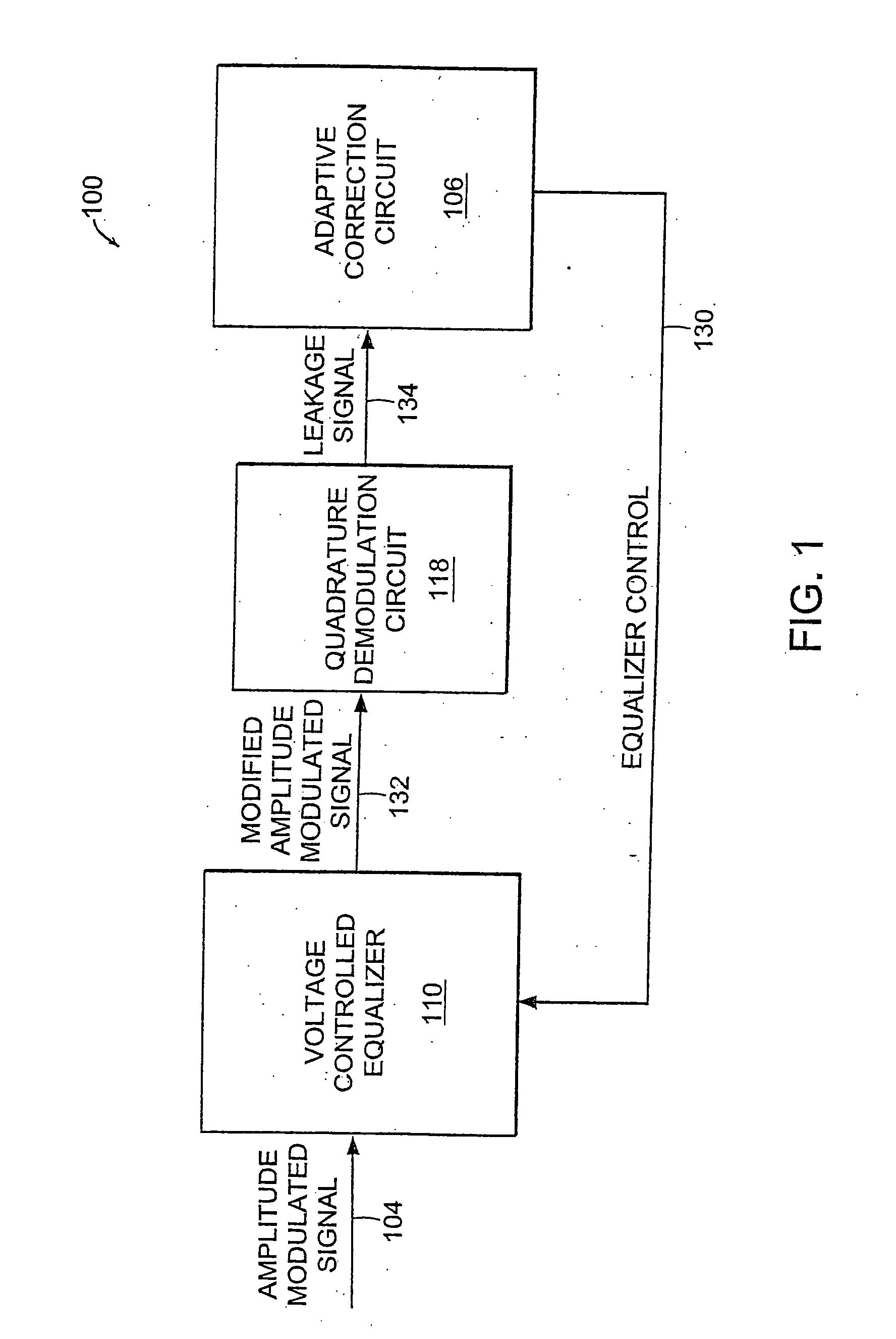
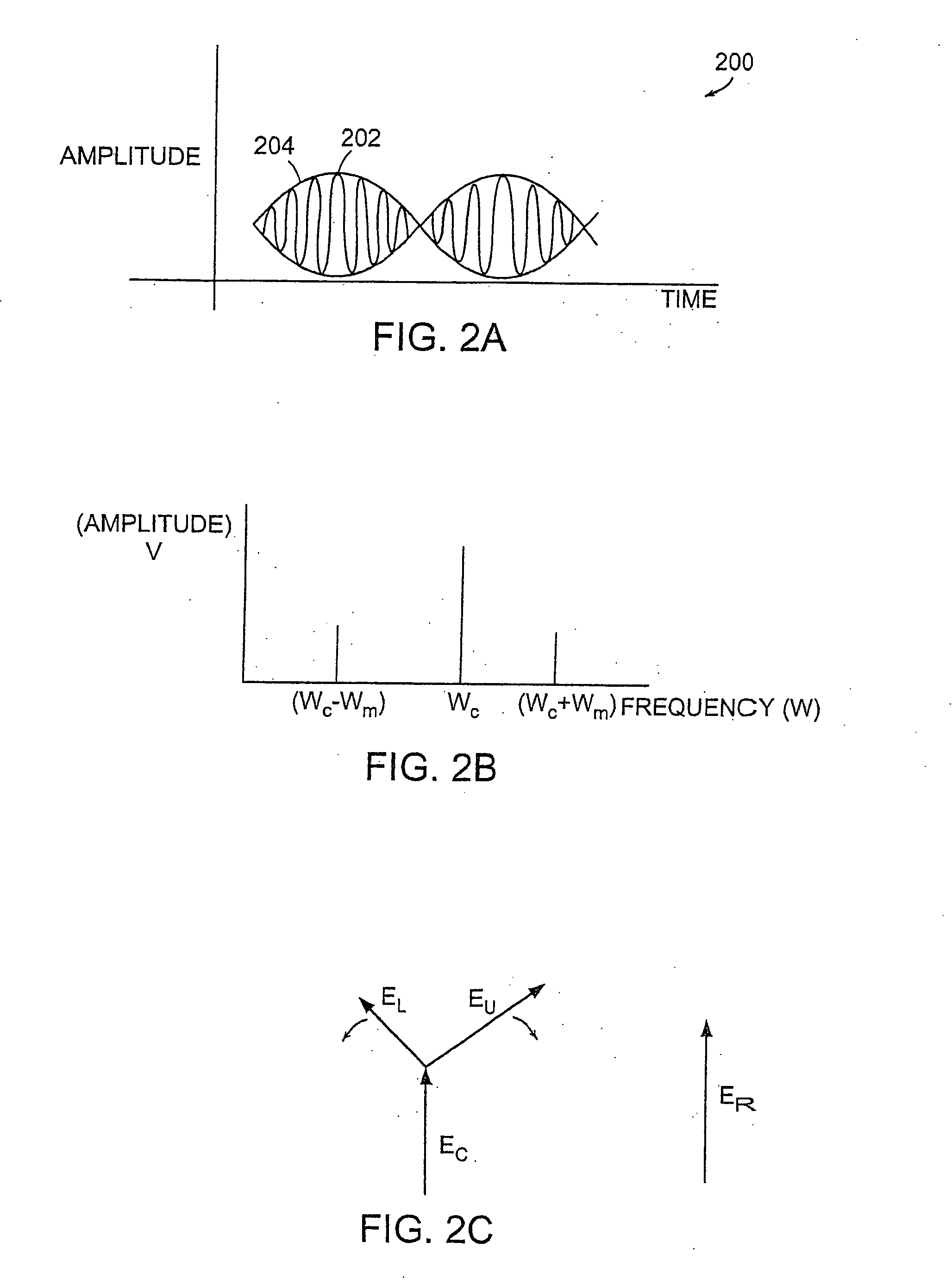
[0022]FIG. 1 is a block diagram of a receiver 100 including an adaptive correction circuit 106 according to the principles of the present invention. The adaptive correction circuit 106 measures “leakage” on the leakage signal 134. The “leakage” is an observable effect caused or induced by spectral slope. The spectral slope is any tilt in the frequency domain. For example, if viewed on a spectrum analyzer, the spectrum of a signal with spectral-slope-induced leakage is non-symmetrical in power around a mid-point in the frequency axis.

[0023] An amplitude modulated signal (“AM”) 104 with distortion induced by channel impairments is processed by a voltage controlled equalizer 110. The voltage controlled equalizer 110 includes a filter having a frequency response selected to approximate the inverse frequency response of the transmission medium over which the AM signal 104 is being transmitted. The inverse frequency ...


PUM


Abstract

Distortion due to transmission characteristics of a transmission medium is corrected by measuring leakage in a signal orthogonal to a received signal. The frequency response of an equalizer is adaptively adjusted until the measured leakage is at a local minimum.

Description

BACKGROUND OF THE INVENTION [0001] An amplitude modulated signal received over a transmission medium can be distorted due to transmission characteristics of the transmission medium, resulting in attenuation of the signal at different frequencies. A receiver typically includes an equalizer for compensating for the distortion due to the frequency response of the transmission medium. Ideally, the frequency response of the transmission medium should be flat; that is, the magnitude of the sidebands should be equal. However, the frequency response can be downward sloping or upward sloping dependent on frequency and phase distortion in the received signal due to the unequal magnitude of the sideband carriers. The frequency response of a filter in the equalizer is generally selected to approximate the inverse frequency response of the transmission medium in order to equalize or “flatten” the frequency response. [0002] The characteristics of the transmission medium or the apparatus used to c...

Claims


Application Information

Patent Timeline
Patent Type & Authority Applications(United States)
IPC IPC(8): H04B1/10H04B17/00H04L25/03H04L27/00
CPCH04L25/03159H04L2025/0342H04B17/354H04L2027/0057H04L2025/03522
Inventor TALBOT, DANIEL B.
Owner CIENA
Why Eureka
Try Eureka