Engine and driveline torque transfer device control

a technology of torque transfer device and engine, which is applied in the direction of coupling-brake combination, instruments, computing, etc., can solve the problems of inability to control the torque converter, inability to adjust the torque, so as to reduce the disturbance of the starting clutch and avoid the effect of affecting the damping characteristics of the starting clutch

Active Publication Date: 2006-01-26
GM GLOBAL TECH OPERATIONS LLC
View PDF10 Cites 24 Cited by
  • Summary
  • Abstract
  • Description
  • Claims
  • Application Information

AI Technical Summary

Benefits of technology

[0006] A vehicular starting clutch control provides responsive vehicle launches and favorable driveline damping during launch, cruising and torque reversals. A driveline damping control is effective during launch and subsequently during slip control to actively attenuate driveline disturbances. Tip-in management is effective to delay changes to clutch capacity until clutch slip has changed direction to reduce any driveline disturbances that may be introduced by rapid torque reversals across the starting clutch.

Problems solved by technology

Torque converters have inherent efficiency shortfalls as some portion of the input energy is lost to the fluid.
While controlled capacity TCC improves upon the fluidic losses of the torque converter, fluid losses still remain as does the substantial hardware and mass—including substantial fluid mass associated with necessary coupling fluid—associated with a torque converter and TCC complement.
However, the inherent damping characteristics (or lack thereof) associated with starting clutches are substantially less ideal than those of the fluidic coupling of the torque converter and present significant challenges to attaining acceptable levels of driveline disturbance in such a system.

Method used


Image

  • Engine and driveline torque transfer device control
  • Engine and driveline torque transfer device control
  • Engine and driveline torque transfer device control

Examples


Embodiment Construction

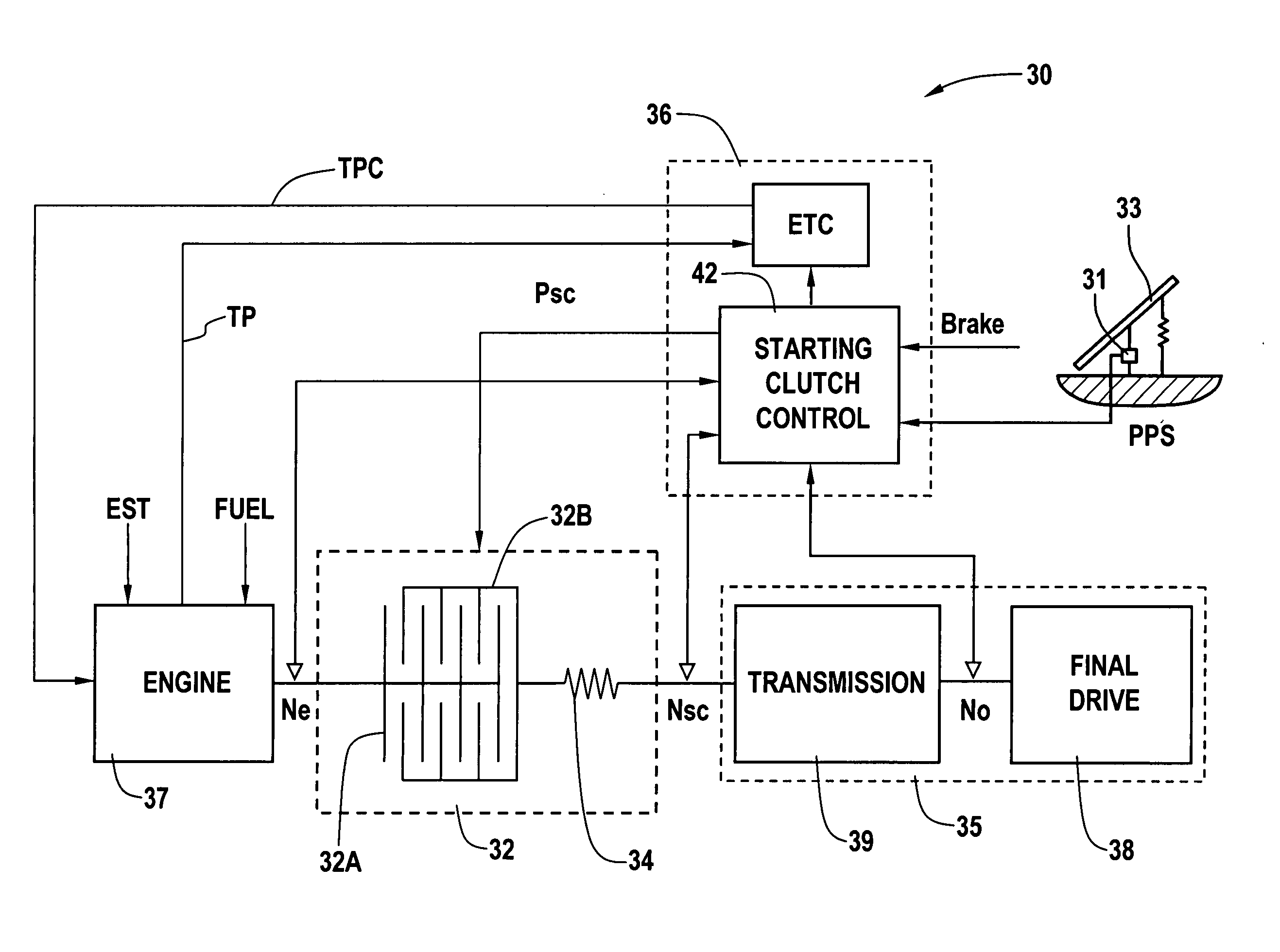
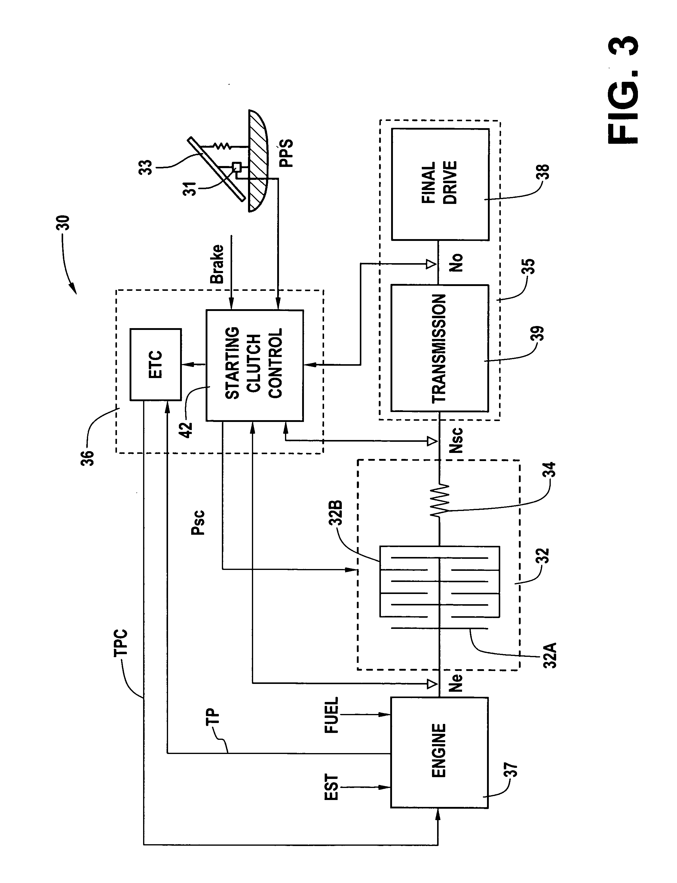
[0021] With reference first to FIG. 3, a vehicular powertrain system 30 includes an internal combustion engine 37 coupled to a driveline 35. The driveline includes a transmission 39, such as a multiple speed ratio transmission having a plurality of forward-speed ratios controlled in accordance with transmission shift controls operative to control electrohydraulic circuits for establishing the various speed ratios and shifts therebetween. The driveline further includes final drive 38 which as used herein includes all other driveline components found after the transmission output including final drive gearsets, differential gearsets, propshafts, halfshafts, constant velocity joints, etc. The engine 37 has an output that is mechanically coupled to one side 32A of a starting clutch 32. The other side 32B of the starting clutch 32 is mechanically coupled to an input member of the transmission 39. Preferably, the starting clutch includes a complement of spring dampers 34 predominantly eff...


PUM


Abstract

A starting clutch control includes an engine control state and a slip control state. The engine and slip control states include feedforward and driveline damping control terms. The engine state control may further include an engine speed control term. The slip control state further includes a clutch slip control term. Changes to clutch engagement commands are frozen upon throttle tip-in events.

Description

TECHNICAL FIELD [0001] The present invention is generally related to vehicular powertrains. More particularly, the invention is concerned with vehicular powertrains wherein engine torque is coupled to the driveline across a controlled capacity torque transfer device in lieu of an hydrostatic torque converter. BACKGROUND OF THE INVENTION [0002] In a conventional automatic transmission drivetrain, a torque converter is located between the crankshaft of an internal combustion engine and a multiple speed ratio transmission. The torque converter functions to provide fluidic coupling of the engine output to the driveline generally at low vehicle speeds (higher transmission speed ratios). Vehicle launch performance is enhanced by the torque converter's torque multiplication effects. And, the fluidic coupling of the torque converter also provides effective decoupling of engine torque pulsations to the driveline and, perhaps more significantly, damping of driveline torsional disturbances bac...

Claims


Application Information

Patent Timeline
Patent Type & Authority Applications(United States)
IPC IPC(8): G06F19/00
CPCB60W10/02B60W10/06B60W30/18027Y10T477/78B60W2510/0638B60W2710/0644B60W30/20
Inventor SMITH, ANTHONY L.USORO, PATRICK B.KAO, CHI-KUAN
Owner GM GLOBAL TECH OPERATIONS LLC
Why Eureka
Try Eureka