Infrared emitting apparatus

a technology of infrared radiation and emitter, which is applied in the direction of stoves, combustion types, ranges, etc., can solve the problems of most flare-ups, uncontrolled burning, and high fire intensity, and achieve the effect of enhancing the emission of infrared radiation and keeping the temperature of the emitter relatively high

Active Publication Date: 2006-02-02
CHAR BROIL
View PDF77 Cites 50 Cited by
  • Summary
  • Abstract
  • Description
  • Claims
  • Application Information

AI Technical Summary

Benefits of technology

[0011] In accordance with one aspect of the present invention, an apparatus for cooking food with infrared radiation includes at least one infrared energy emitter for emitting at least the infrared radiation, and at least one grid, or the like, in close proximity to the infrared energy emitter. A first side of the grid can be for supporting the food at a position so that at least some of the infrared radiation will cook the food. A second side of the grid can be sufficiently close to the emitting side of the emitter for substantially restricting any airflow in any space between the second side of the grid and the emitting side of the emitter. Such restricting of airflow advantageously seeks to overcome problems associated with flare-up, by restricting the amount of oxygen that is available proximate the emitting side of the emitter. Such restricting of airflow can also advantageously restrict convective cooling of the infrared energy emitter, which can help to keep the temperature of the emitter relatively high and, therefore, enhance the emission of infrared radiation from the emitter.
[0012] In accordance with one aspect of the present invention, the grid, or the like, can include partitions that are in a predetermined configuration and adjacent to the emitting side of the emitter so that the emitting side of the emitter is operatively segregated into segments. This segregating into segments can advantageously provide a substantially uniform distribution of infrared radiation. For example, the partitions and the segments can respectively cooperatively define a plurality of cavities or open chambers, or the like. Each of the cavities can include an inner portion and an outer opening, with the outer opening being farther from the emitting side of the emitter than the inner portion of the cavity. For each cavity, substantially all of the energy emitted from the segment of the emitter that at least partially defines the inner portion of the cavity can exit the outer opening of the cavity as radiant energy, which can be advantageous.

Problems solved by technology

One problem common to the prior art types of grills is flare-ups.
When cooking, most flare-ups (uncontrolled burning) are caused when oils, discharged from the fat in the meat being cooked, ignite.
In the early cycle of the cooking process, it is common practice to sear the meat, which requires high fire.
Therefore, it is difficult to cook or broil meat containing fat fast enough to sear and mark the meat properly without causing flare-ups (causing excessive charring).
However, these types of grills are designed for very slow cooking and are not usually used for cooking a variety of meat cuts such as steak, hamburgers, pork chops, and lamb chops.
Also, these types of slow cooking grills are seldom used in commercial applications.
The problems with flare-ups or uncontrolled burning are especially bothersome in commercial use because of the large quantities of meat being prepared at the same time.
The larger cooking surfaces of these types of grills allow for more meat to be cooked or broiled at the same time, expelling more oil from the fat onto the grill creating the potential for large flare-ups.
When conventional grills are heated to a level to accomplish the desired cooking times, flare-up becomes a constant problem if the meat contains even a moderate amount of fat.
Another problem typical of prior art types of grills is that the energy is not distributed uniformly over the cooking grid surface.
This report covers commercial types of grills, but the same problem exists with consumer types of grills.
This particular problem with prior art types of grills impedes the cooking or broiling process and requires the chef to redistribute the food over the cooking grids in order to ensure energy absorption uniformity.
Therefore, it is often difficult for even experienced chefs to cook or broil multiple pieces of meat to the same level of being done.
While flare-ups and poor heat distribution impose operational problems, typical prior art types of grills are also very inefficient.
The problem is less pronounced in the use of consumer grills because of briefer cooking periods.
However, in commercial use this problem is more pronounced because many grills operate in excess of 12 hours each day.
It is likely that flare-up is considered as a necessary evil of a hot grill.

Method used


Image

  • Infrared emitting apparatus
  • Infrared emitting apparatus
  • Infrared emitting apparatus

Examples


Embodiment Construction

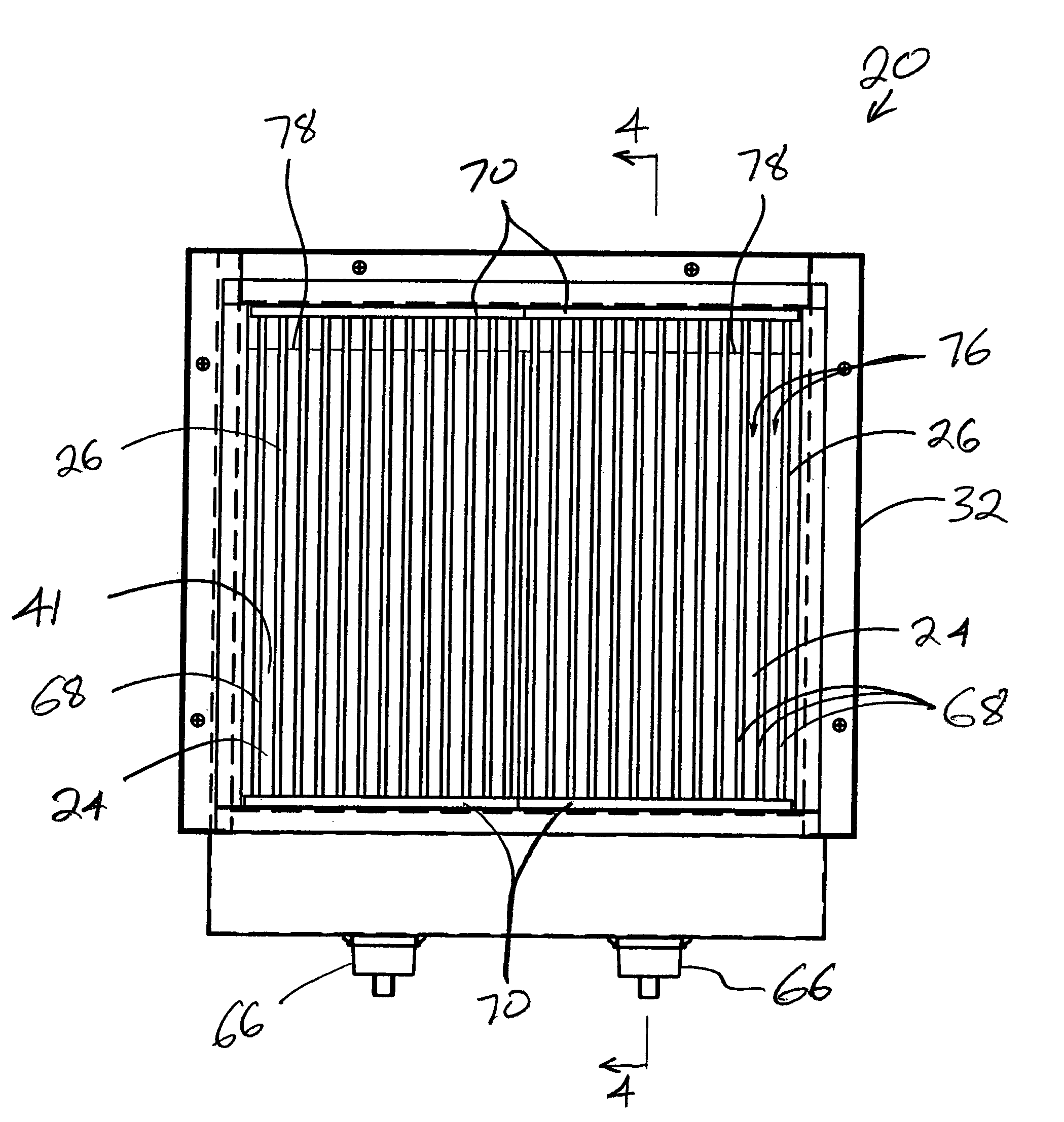
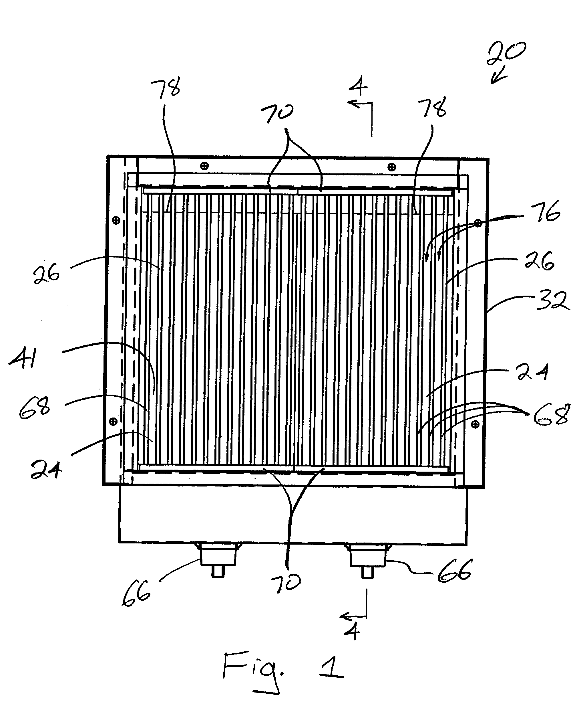
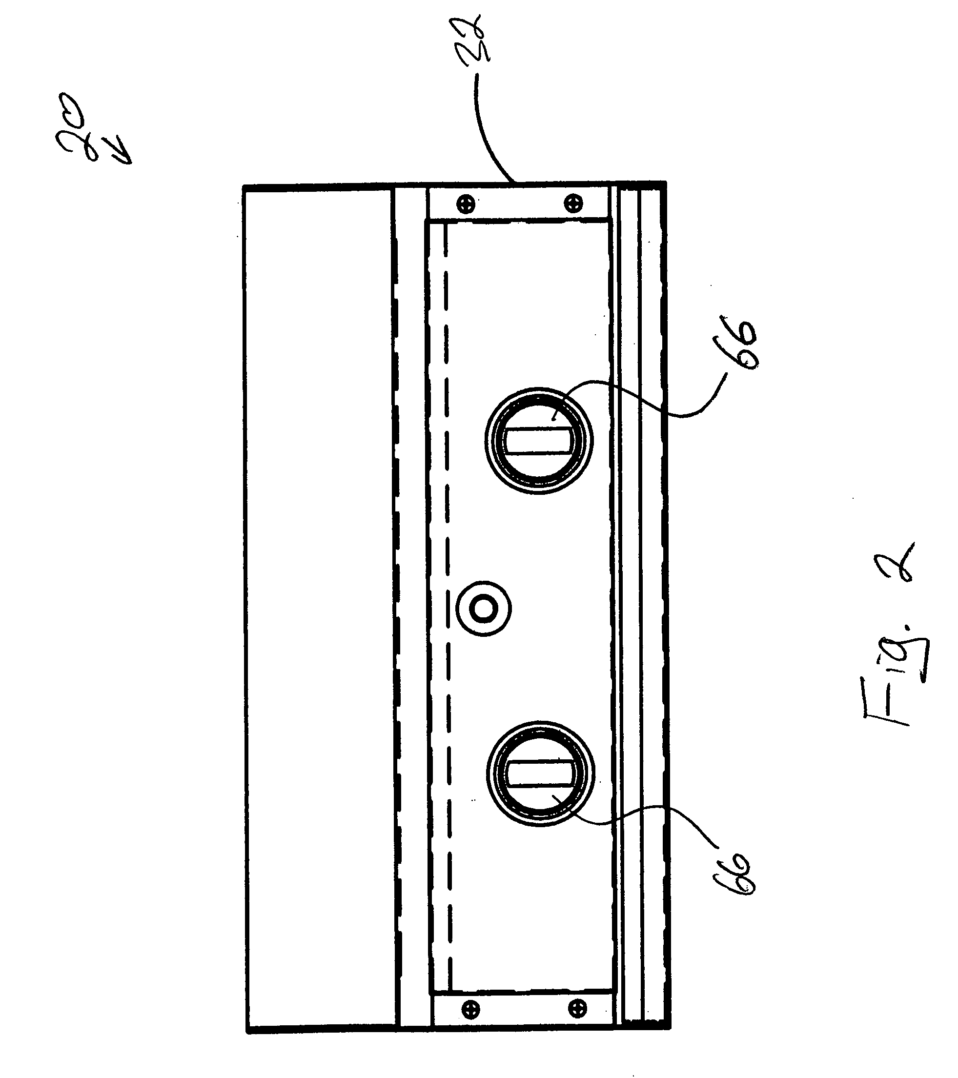
[0024] Referring now in greater detail to the drawings, in which like numerals refer to like parts throughout the several views, FIGS. 1-4 schematically illustrate a cooking apparatus 20 (e.g., broiler or grill) that includes two sources of energy (e.g., heating units 22), with each of the heating units being respectively associated with an infrared radiant energy emitter 24 and a grid 26, in accordance with an exemplary embodiment of the present invention. The heating units 22 function to heat the energy emitters 24 so that the energy emitters emit infrared radiation, such as for cooking (e.g., broiling) food on the grids 26. The energy emitters 24 can be heated in any conventional manner. For example, the heating units 22 can be gas burners or electrical heating elements, or the like. Nonetheless and not for the purpose of narrowing the scope of the present invention, the heating units 22 are described herein as being infrared radiant burner units 22.

[0025] Very generally describ...


PUM


Abstract

An apparatus for cooking food with infrared radiation includes an infrared energy emitter for emitting the infrared radiation, and a grid in close proximity to the infrared energy emitter. A first side of the grid can be for supporting the food at a position so that at least some of the infrared radiation will cook the food. A second side of the grid can be sufficiently close to the emitting side of the emitter for substantially restricting any airflow in any space between the second side of the grid and the emitting side of the emitter. Partitions of the grid can operatively segregate the emitting side of the emitter into segments, which can provide a substantially uniform distribution of infrared radiation.

Description

CROSS-REFERENCE TO RELATED APPLICATIONS [0001] The present application claims the benefit of both U.S. Provisional Application No. 60 / 582,276, filed Jun. 23, 2004, and U.S. Provisional Application No. 60 / 591,215, filed Jul. 26, 2004. Each of the above-referenced provisional applications is incorporated herein by reference, in its entirety. Also incorporated herein by reference, in its entirety, is the U.S. utility patent application that is entitled “Radiant Burner,” names Willie H. Best as the inventor, and has been filed on the same day as the present application.TECHNICAL FIELD [0002] The present invention relates to infrared radiant energy emitters and, more particularly, to infrared radiant energy emitters used with gas-fired infrared burners and / or gratings for cooking food. BACKGROUND OF THE INVENTION [0003] There are various types of gas grills or broilers on the market sold under a variety of brand names. The majority of these grills use a conventional port type gas burner ...

Claims


Application Information

Patent Timeline
Patent Type & Authority Applications(United States)
IPC IPC(8): A23L3/28
CPCA23L1/0128A47J37/0676A47J37/0682F23D14/14F23D2900/14123F23D2203/1026F23D2203/106F23D2212/20F23D2203/1023A23L5/15F23D14/147
Inventor BEST, WILLIE H.
Owner CHAR BROIL
Why Eureka
Try Eureka