Shower head structure and treating device

a technology of treating device and shower head, which is applied in the direction of liquid surface applicators, chemical vapor deposition coatings, coatings, etc., can solve the problems of increasing the amount of nonreactive gas to be used, the uniform thickness of the film in the in-surface of the wafer becomes deteriorated, and the radiant thermometer cannot accurately measure the temperature of the wafer, etc., to suppress the adhesion preventive gas, reduce the flow rate of adhesion preventive gas to reduce the effect o

Inactive Publication Date: 2006-02-02
TOKYO ELECTRON LTD
View PDF2 Cites 61 Cited by
  • Summary
  • Abstract
  • Description
  • Claims
  • Application Information

AI Technical Summary

Benefits of technology

[0025] In accordance with still another aspect of the present invention, there is provided a shower head structure including: a shower head section provided to face a top surface of a mounting table in an evacuatable treating vessel; a multiplicity of gas injection holes, opened in a lower surface of the shower head section, for injecting a processing gas into the treating vessel; a temperature observation through hole opened in the lower surface of the shower head section to face the top surface of the mounting table; a transparent observation window for airtightly sealing an upper portion of the temperature observation through hole; a radiant thermometer provided at a top surface side of the transparent observation window; and an adhesion preventive gas supply path, communicating with the temperature observation through hole, for supplying thereinto an adhesion preventive gas, which prevents a film from being deposited on the transparent observation window, wherein a gas discharge passage, communicating with the temperature observation through hole, for discharging the adhesion preventive gas supplied from the adhesion preventive gas supply path into the temperature observation through hole, is installed.
[0026] In accordance with the present invention, a gas discharge passage for discharging the adhesion preventive gas supplied from the adhesion preventive gas supply path into the temperature observation through hole is installed, so that it is possible to effectively prevent the surface of the transparent observation window from making a contact with the processing gas, even though the flow rate of the adhesion preventive gas is small. Further, it is possible to remarkably suppress the adhesion preventive gas from affecting the processing on the object through the temperature observation through hole. For example, in case of a thin film forming processing on the surface of the object, in-surface uniformity in a film thickness can be maintained high.

Problems solved by technology

However, what the aforementioned thermocouple directly detects is the temperature of the mounting table, not that of the wafer as described above.
However, if a residual thin film is deposited to be adsorbed on a surface of a light detector of the radiant thermometer on which an incident light of specific wavelength band from the wafer is to be illuminated, the light is absorbed by the thin film, and therefore, the radiant thermometer cannot measure the temperature of the wafer accurately.
As a result, a film thickness of a portion, into which the nonreactive gas is introduced, is changed, so that uniformity in the film thickness of in-surface of the wafer becomes deteriorated.
Further, an increase in the amount of nonreactive gas to be used is problematic.

Method used


Image

  • Shower head structure and treating device
  • Shower head structure and treating device
  • Shower head structure and treating device

Examples


first embodiment

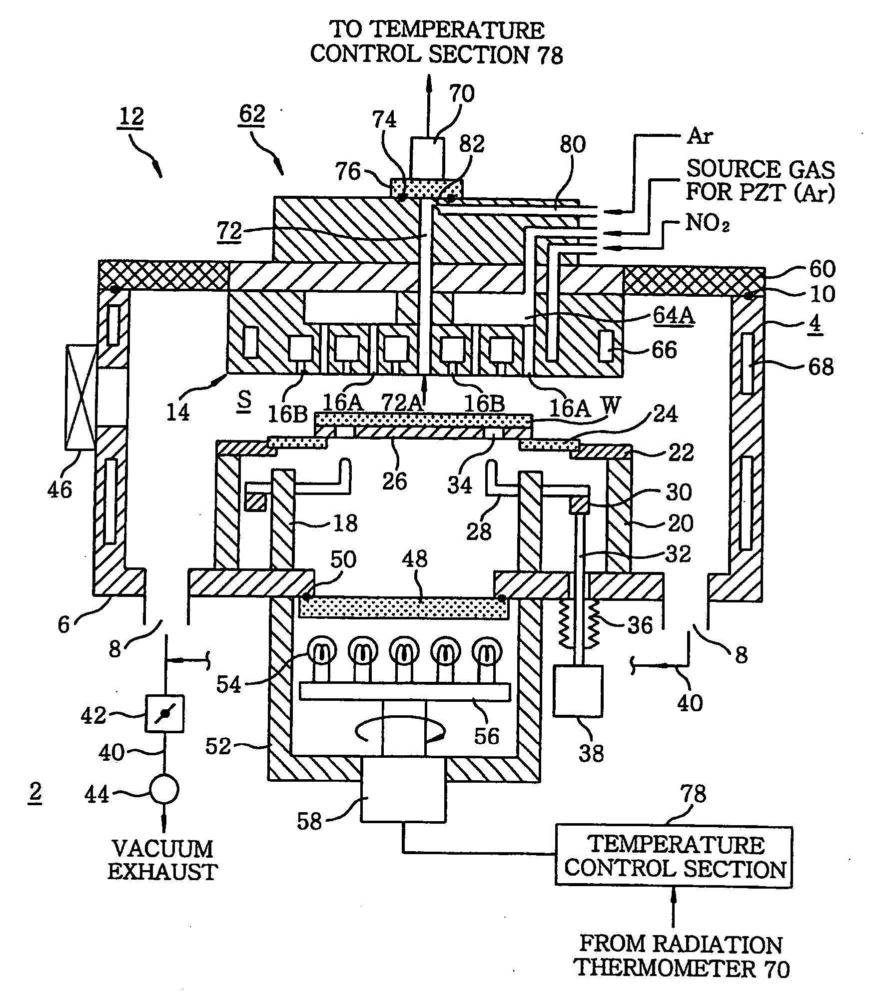
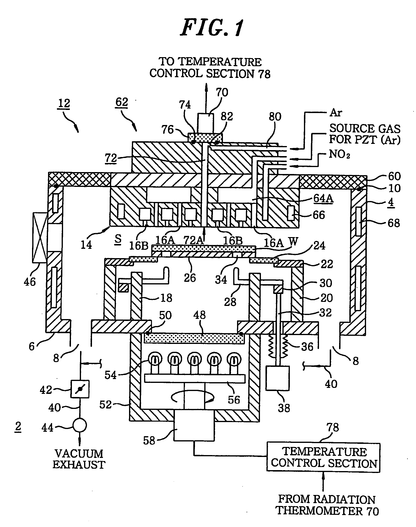
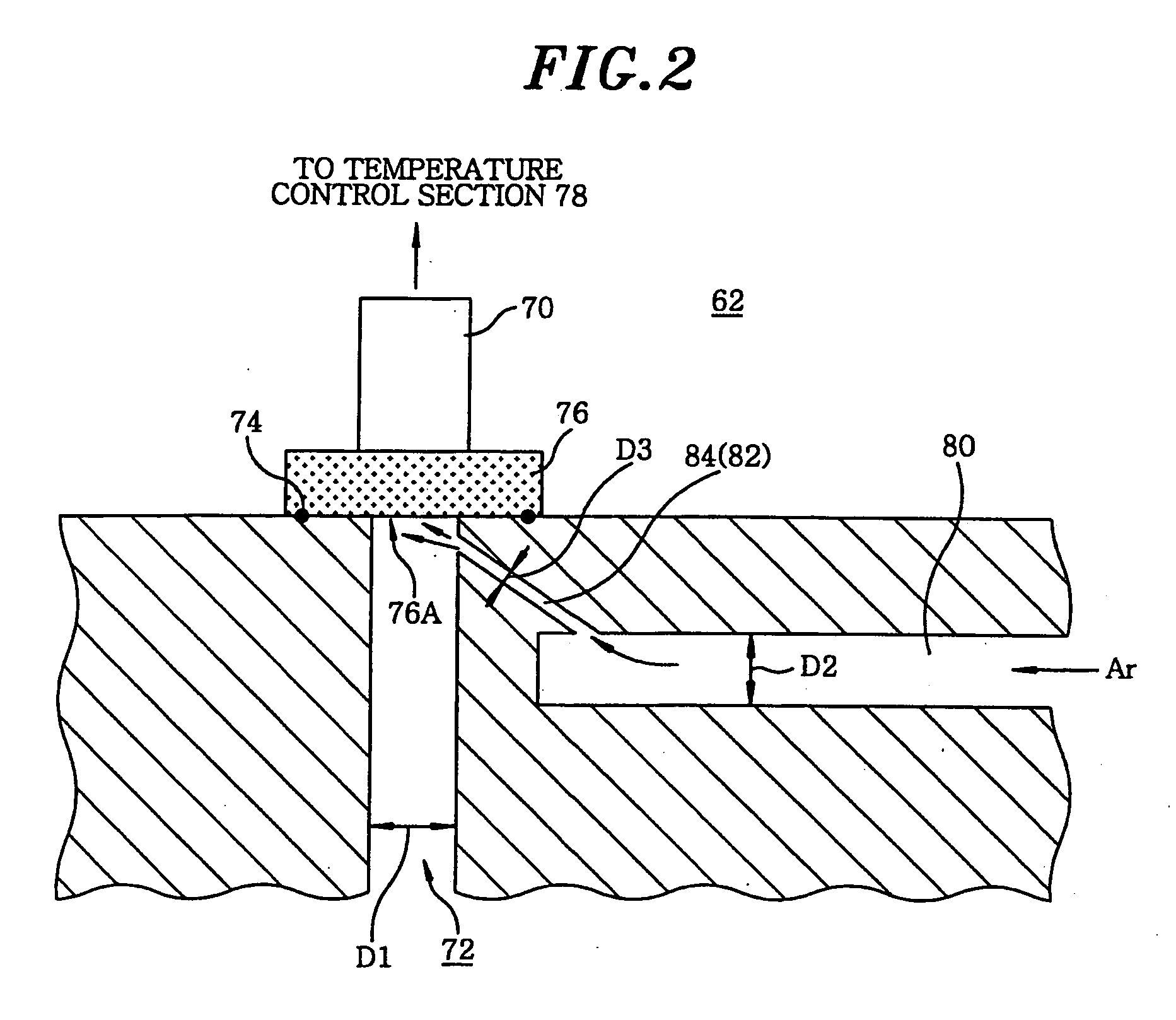
[0052]FIG. 1 is a cross sectional configuration view showing a processing device having a shower head structure in accordance with a first embodiment of the present invention; and FIG. 2 is a magnified cross sectional view showing a part of the shower head structure shown in FIG. 1. Herein, as a heat treatment, a case of forming a PZT film of a metal oxide film by CVD will be discussed as an example.

[0053] As illustrated in FIG. 1, a processing device 2 has a cylindrical treating vessel 4 made of, e.g., aluminum. A gas exhaust port 8 is installed at a bottom portion 6 of the treating vessel 4. An inside of the treating vessel 4 is configured to be vacuum-exhausted through the gas exhaust port 8. At a ceiling portion of the treating vessel 4, a shower head structure 12 is installed through a sealing member 10 such as an 0-ring or the like. A multiplicity of gas injection holes 16A and 16B is provided in a gas injection surface 14 of a lower surface of the shower head structure 12. A...

second embodiment

[0075] In the following, a second embodiment of the present invention will be discussed.

[0076]FIG. 3 is a magnified partial cross sectional view showing a part of a shower head structure in accordance with a second embodiment of the invention.

[0077] Further, in FIG. 3, identical reference numerals will be used for the parts having substantially same functions as those in FIG. 2, and redundant description thereof will be omitted.

[0078] In the first embodiment shown in FIG. 2, the injection nozzle unit 82 at the end portion of the adhesion preventive gas supply path 80 is formed by carrying out a boring processing on the purge injection hole 84. On the other hand, in the second embodiment shown in FIG. 3, the injection nozzle unit 82 is formed by a gas injection pipe 90 made of a heat-resistant transparent material. Specifically, the gas injection pipe 90 is formed by bending, e.g., a transparent slim quartz glass tube to make it have a substantially L-shape; and it is attached to ...

third embodiment

[0081] In the following, a third embodiment of the present invention will be explained.

[0082]FIG. 4 is a magnified cross sectional view showing a part of a shower head structure in accordance with a third embodiment of the invention; FIG. 5 is a perspective view showing a gas diffusion groove shown in FIG. 4; and FIG. 6 is a plane view showing the gas diffusion groove shown in FIG. 4. Further, in FIG. 4, identical reference numerals will be used for the parts having substantially same functions as those in FIGS. 2 and 3, and redundant description thereof will be omitted.

[0083] In the third embodiment shown in FIG. 4, at the upper portion of the temperature observation through hole 72, a circular ring-shaped gas diffusion groove 96 is formed to enlarge the radius of the temperature observation through hole 72. The transparent observation window 76 is attached to airtightly shut the entire gas diffusion groove 96. Further, a hole 96A formed at a bottom portion of the gas diffusion g...


PUM

PropertyMeasurementUnit
temperatureaaaaaaaaaa
diameter D1aaaaaaaaaa
inner diameter D2aaaaaaaaaa

Abstract

A shower head structure characterized by comprising a shower head section, opposed to the upper surface of a mounting table in an evacuable treating vessel, for injecting a processing gas into the treating vessel; a temperature observation through-hole which opens in the lower surface of the shower head so as to be opposed to the upper surface of the mounting table, a transparent observation window which hermetically seals the upper end of the temperature observation through-hole, a radiation thermometer disposed on the upper surface of the transparent observation window, an adhesion preventive gas supply path communicating with the temperature observation through-hole to prevent a film from adhering to the transparent observation window, wherein the adhesion preventive gas supply path communicates with the temperature observation through-hole through an injection nozzle for injecting the adhesion preventive gas to the transparent observation window.

Description

[0001] This application is a Continuation Application of PCT International Application No. PCT / JP04 / 005172 filed on Apr. 9, 2004, which designated the United States.FIELD OF THE INVENTION [0002] The present invention relates to a shower head structure and a processing device for performing a heat treatment such as a film forming processing of, e.g., a metal oxide film, or an etching processing or the like, on an object to be processed such as a semiconductor wafer or the like. BACKGROUND OF THE INVENTION [0003] Generally, for producing a desired semiconductor device, a heat treatment such as a film forming processing or a pattern etching processing or the like is repeatedly performed on a semiconductor wafer. With a recent trend towards high-density and high-integration of a semiconductor device, a strict heat treatment method has been demanded. For example, for a very thin oxide film such as an insulating film of a capacitor or a gate insulating film in the device, the film is also...

Claims


Application Information

Patent Timeline
Patent Type & Authority Applications(United States)
IPC IPC(8): B05C11/00C23C16/44C23C16/455H01L21/00H01L21/205
CPCC23C16/455H01L21/67248H01L21/67017C23C16/45565C23C16/4408
Inventor MATSUMOTO, KENJI
Owner TOKYO ELECTRON LTD
Why Eureka
Try Eureka