Ignition timing control apparatus for internal combustion engine

Inactive Publication Date: 2006-02-02
TOYOTA JIDOSHA KK
View PDF12 Cites 29 Cited by
  • Summary
  • Abstract
  • Description
  • Claims
  • Application Information

AI Technical Summary

Benefits of technology

[0009] In view of the foregoing conventional problems, an object of the present invention is to provide an ignition timing control apparatus for an internal com

Problems solved by technology

A resultant problem is that, if ignition is simply caused for operation based on an ignition timing value that is set according to an operation state, the ignition timing is improper.
Otherwise, such abnormal combustion as knocking occurs or the output power is insufficient.
I

Method used


Image

  • Ignition timing control apparatus for internal combustion engine
  • Ignition timing control apparatus for internal combustion engine
  • Ignition timing control apparatus for internal combustion engine

Examples


Embodiment Construction

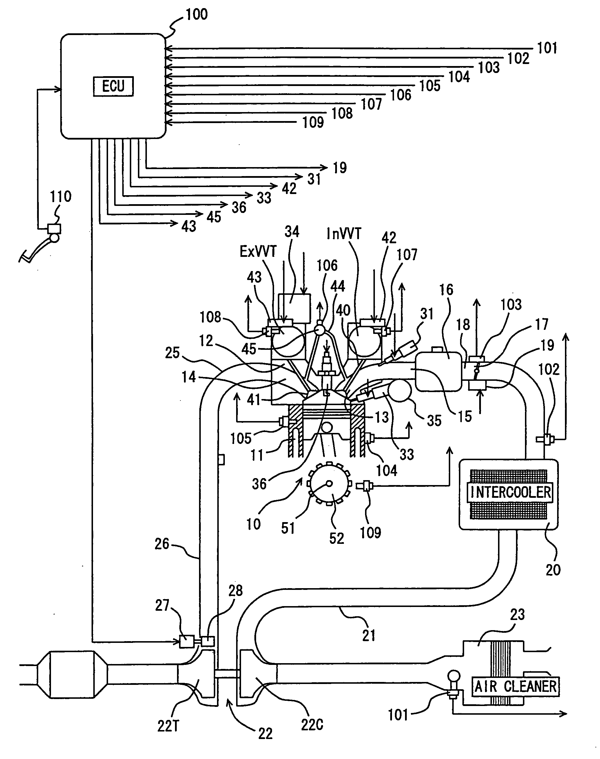
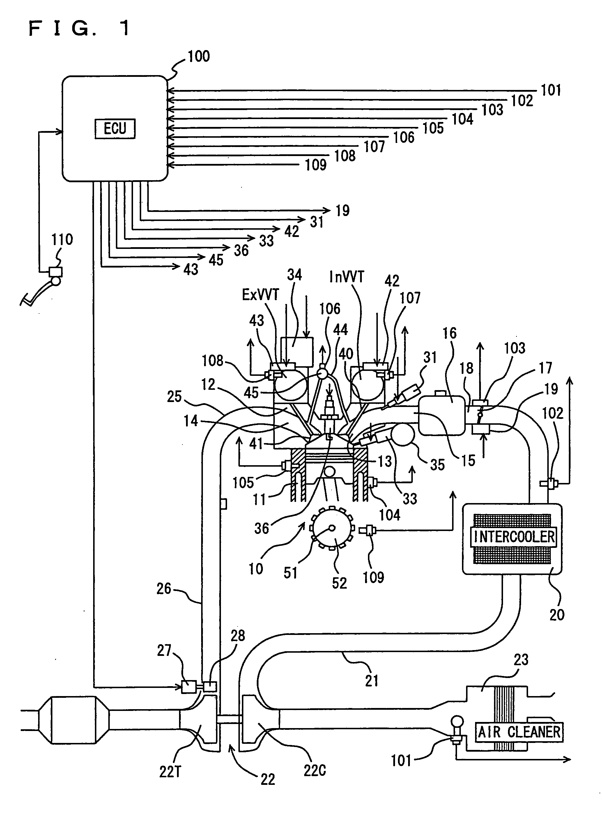
[0021] Hereinafter, embodiments of the present invention will be described with reference to the drawings. Firstly, an overall configuration of an internal combustion engine of a duel injection type to which the present invention is adapted will be described with reference to FIG. 1.

[0022]FIG. 1 shows an engine with a variable valve timing mechanism and a supercharger (hereinafter, simply referred to as “engine”) 10. In FIG. 1, a gasoline engine having an intake port injector 31 and an in-cylinder injector 33 is shown. On top of a cylinder block 11 of engine 10, a cylinder head 12 is provided, in which an intake port 13 and an exhaust port 14 are formed for each cylinder.

[0023] As an intake system of engine 10, each intake port 13 is connected to an intake manifold 15, which in turn is connected to a throttle chamber 18 fitted with a throttle valve 17, via a surge tank 16 to which intake paths of the respective cylinders are collectively connected. Throttle valve 17 is driven by a...


PUM


Abstract

An ignition timing control apparatus for an internal combustion engine having an in-cylinder injector for injecting a fuel into a cylinder and an intake port injector for injecting a fuel into an intake port is configured to correct a basic ignition timing, having been determined corresponding to an operation state, in accordance with a fluctuation of at least one factor affecting the combustion rate selected from a coolant temperature, an intake air temperature and an EGR (exhaust gas recirculation) amount, to set a final ignition timing. The correction amount of the ignition timing is set greater for the port injection than for the in-cylinder injection.

Description

[0001] This nonprovisional application is based on Japanese Patent Application No. 2004-224715 filed with the Japan Patent Office on Jul. 30, 2004, the entire contents of which are hereby incorporated by reference. BACKGROUND OF THE INVENTION [0002] 1. Field of the Invention [0003] The present invention relates to an ignition timing control apparatus for an internal combustion engine, and more particularly to an ignition timing control apparatus for a so-called dual injection type internal combustion engine that is provided with an in-cylinder injector for injecting a fuel into a cylinder and an intake port injector for injecting a fuel into an intake port. [0004] 2. Description of the Background Art [0005] An internal combustion engine of so-called dual injection type is known from Japanese Patent Laying-Open No. 2001-020837. This internal combustion engine includes an in-cylinder injector for injecting a fuel into a cylinder and an intake port injector for injecting a fuel into an...

Claims


Application Information

Patent Timeline
IPC IPC(8): F02B5/00F02B7/00F02D41/24F02D41/30F02P5/15
CPCF02D41/2422F02D41/3029Y02T10/46F02P5/1502F02P5/1516F02D41/3094Y02T10/40
Inventor MIYASHITA, SHIGEKI
Owner TOYOTA JIDOSHA KK
Why Eureka
Try Eureka