Home security system

a home security and system technology, applied in the field of security systems, can solve the problems of difficult to block impersonations or interceptions by a third party, disastrous situation, and the conventional home security system described above does not perform a rigorous authentication procedure, and achieve the effect of facilitating operations

Inactive Publication Date: 2006-02-02
AMERICAN TECH GRP JAPAN
View PDF3 Cites 410 Cited by
  • Summary
  • Abstract
  • Description
  • Claims
  • Application Information

AI Technical Summary

Benefits of technology

[0019] The present invention has the following effects. First, the home security system according to the present invention is capable of preventing nearly all attempts to break into the network by an uncontracted third party through fraudulent use of the authorizing means. Such intrusions are prevented by introducing a fingerprint checking system for checking the fingerprints of a user using a portable terminal such as a cellular telephone, and a sophisticated authentication procedure using a home security stick provided with a unique I

Problems solved by technology

However, the conventional home security system described above does not perform a rigorous authentication procedure to determine whether the user of the cellular telephone is the correct user.
Therefore, it is difficult to block impersonations or interceptions by a third party.
If the system does not detect impersonation by a third party with criminal intent and allows access to this person, the system is actually providing details of the interior of the home including the whereabouts of alarms to the criminal via the internet, even instructing the criminal how to deactivate the alarm

Method used


Image

  • Home security system
  • Home security system
  • Home security system

Examples


Embodiment Construction

[0076] Next, a home security system according to a preferred embodiment of the present invention will be described while referring to the accompanying drawings.

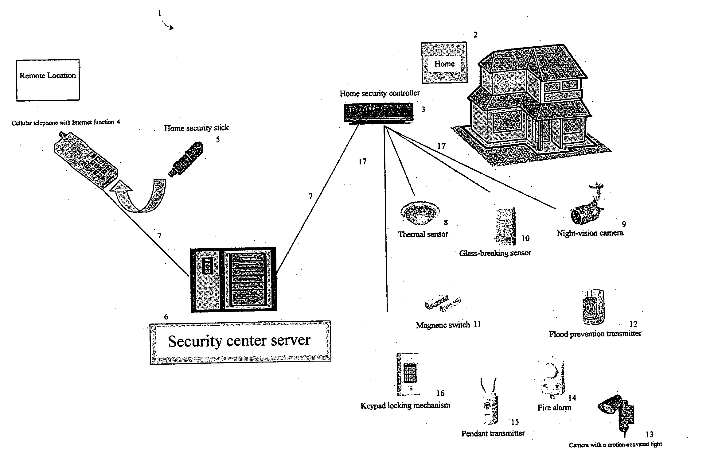
[0077]FIG. 1 is a block diagram showing a home security system 1 according to the preferred embodiment. As shown in FIG. 1, the home security system 1 includes an internet 7, a home security controller 3 installed in a home 2 and connected to the internet 7 through a broadband connection, a cellular telephone 4 that can also connect to the internet 7, and a security center server 6 provided on the internet 7 for managing the entire home security system.

[0078] The home 2 may be a residential home, an office, or a similar space. The home security controller 3 is installed in the home 2 and includes various functions such as an internet firewall, gateway, and wireless LAN router compatible with asymmetric digital subscriber line (ADSL), cable television (CATV), fiber to the home (FTTH), or other types of broadband internet.

[0...


PUM


Abstract

The present invention provides a home security system that includes a home security controller for collecting monitor data from various crime prevention and disaster prevention sensors installed in a home via a home network and notifying the portable terminal when a state of emergency occurs. The home security controller also enables devices in the home to be operated through remote control signals via an external network. The home security system further includes a portable terminal capable of connecting to the external network and having fingerprint data inputting means mounted on the body of the portable terminal for inputting fingerprints used for authentication. The fingerprint data inputting means has an assigned ID number. The home security system further includes a security center server having fingerprint authenticating means for receiving fingerprint data from the portable terminal via the external network and authenticating the fingerprint data through comparisons with registered fingerprint data. The fingerprint authenticating means completes authentication by checking the assigned ID number of the fingerprint data inputting means and matching the received fingerprint data with fingerprint data registered in association with the ID number. The security center server allows a connection between the portable terminal and the home security controller and controls bi-directional communications between the two after the security center server has completed authentication, enabling the portable terminal to receive monitor data from and transmit remote control signals to the home security controller via the external network.

Description

BACKGROUND OF THE INVENTION [0001] The present invention relates to a security system that enables a user, through a portable terminal, to monitor the state of a home whose occupants are away and to control various devices in the home from a remote location. The present invention particularly relates to a home security system capable of preventing a third party from breaking into a home network through fraudulent use of a portable terminal. [0002] There has been a recent increase in the popularity of sophisticated cellular telephones with functions for accessing the Internet and performing broadband communications to display images and the like. For example, the home security system disclosed in Japanese unexamined patent application publication No. 2004-128821 enables a user away from home to monitor the conditions of the user's unoccupied home and perform remote control operations via the Internet or another network using a cellular telephone. [0003]FIG. 8 is a block diagram showi...

Claims


Application Information

Patent Timeline
IPC IPC(8): G08B19/00G08B1/00G05B19/00
CPCH04M11/04G08B25/006
Inventor YUKAWA, MITSUHIKO
Owner AMERICAN TECH GRP JAPAN
Why Eureka
Try Eureka