Wire/fiber ring and method for manufacturing the same

Inactive Publication Date: 2006-02-02
FMW COMPOSITE SYST
View PDF4 Cites 1 Cited by
  • Summary
  • Abstract
  • Description
  • Claims
  • Application Information

AI Technical Summary

Benefits of technology

[0011] Accordingly, it is an object of the present invention to provide an improved TMC wire / fiber ring structure and a method of manufacturing the same wherein there is an unambiguous position choice for each element in each layer.
[0012] It is a further object of the invention to provide a TMC wire / fiber ring that is low in void and has fiber fraction within a desirable range.
[0016] To achieve these and other objects, the present invention provides a composite ring having as a first layer a plurality of first strands or elements each having a first diameter and being spaced from each other with a predetermined distance. A plurality of second strands each having a second diameter different from the first diameter, are disposed such that at least two of the second strands fit between adjacent first strands, thereby completing the first layer.

Problems solved by technology

However, both also restrict manufacturing flexibility in ways critical to design.
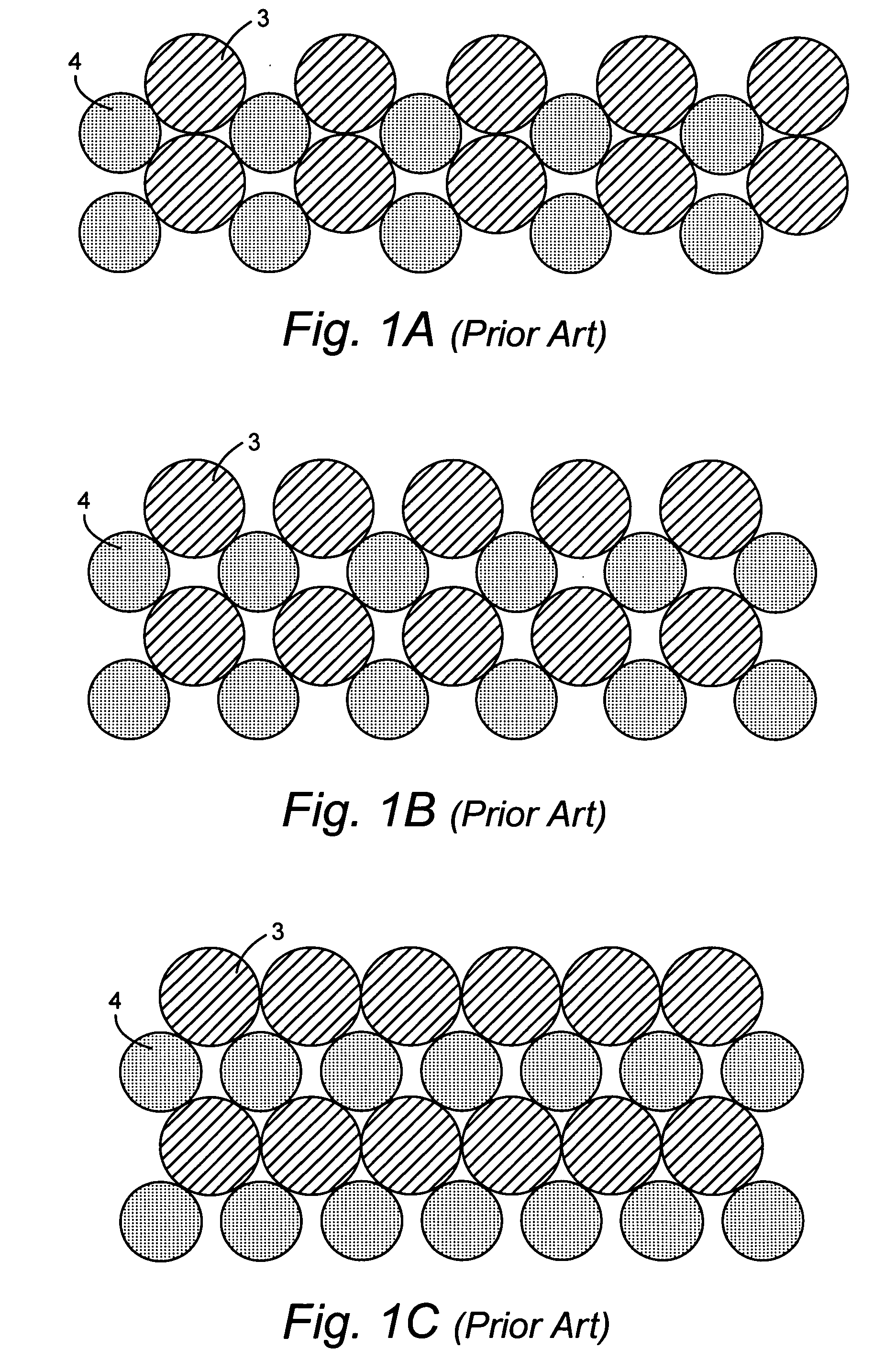
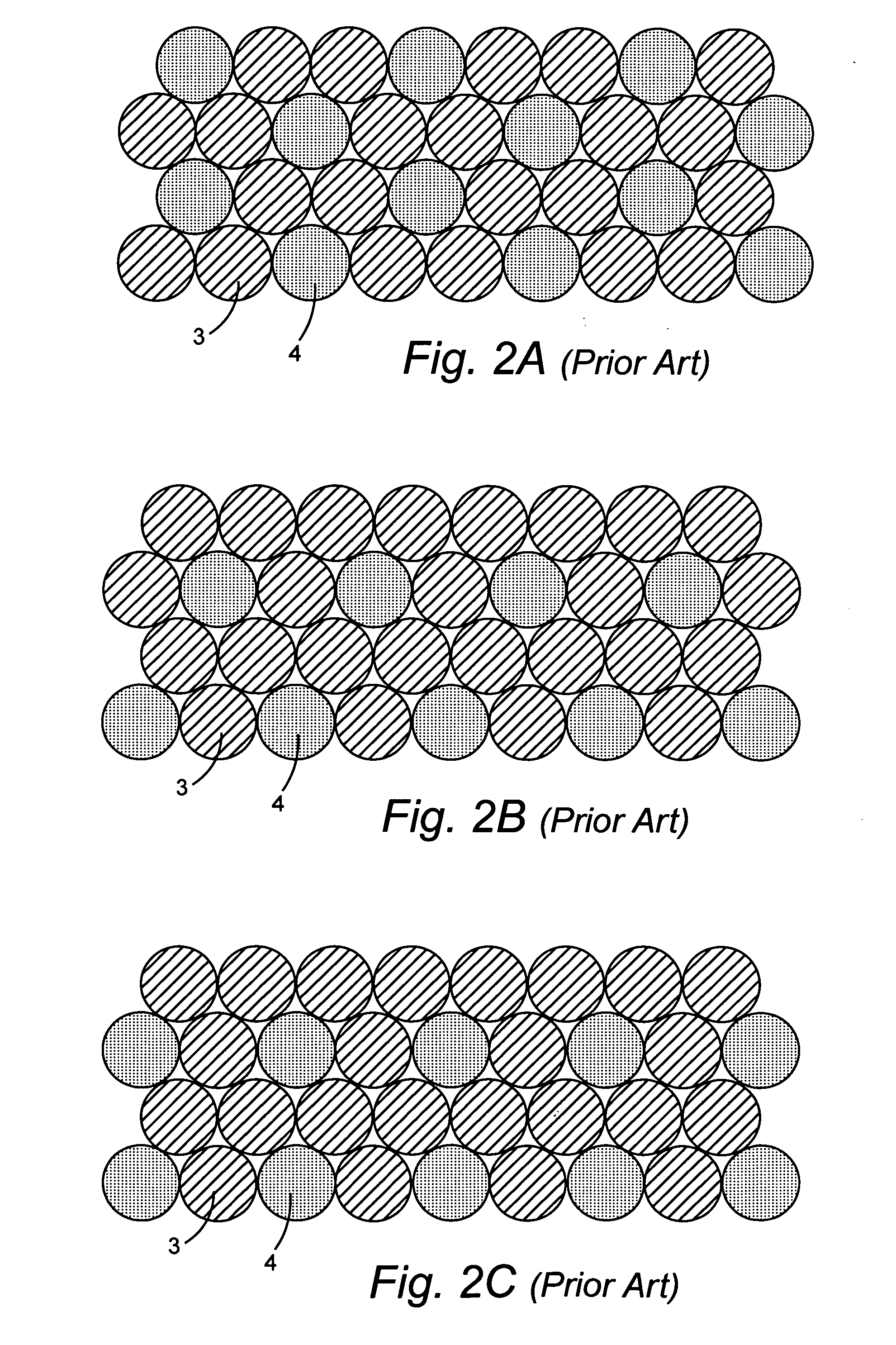
The disadvantage of the structure according to Hanusiak et al., however, is that the assembled array contains about 20% void, which is particularly detrimental in thick parts because it allows for undesirable cusp formation during metal movement.
Moreover, the structure according to Hanusiak et al. has been shown to be organizationally unstable during a consolidation cycle to remove the void content of the TMC part.
The disadvantage, however, of the Bachelet approach is the limitation in the examples to equal diameters for the wires and fibers, which limits the fiber fraction to 25% or 33%.
These fiber fractions are not in the most desirable range from a design standpoint.
Additionally, all examples disclosed in the Hanusiak et al. and Bachelet patens are limited to equal-sized elements in any single layer.
Namely, when dissimilar-sized elements are provided in a single layer and all elements in a layer are applied to the winding core simultaneously there occurs an inherent stacking, or organizational, instability.
That is, the non-equal element size in a given layer creates competition for nesting sites if the subsequent layer elements arrive at the same time.

Method used


Image

  • Wire/fiber ring and method for manufacturing the same
  • Wire/fiber ring and method for manufacturing the same
  • Wire/fiber ring and method for manufacturing the same

Examples


Embodiment Construction

[0046] The preferred embodiments of the present invention will now be described with reference to FIGS. 4A-E and FIG. 5. In accordance with the present invention, an improved method has been identified that achieves a wire / fiber ring having a low void content and a stable array concurrently with flexibility in fiber fraction of between about 0% to 70% and preferably between about 30% and 45%.

[0047] In accordance with the present invention, stacking is controlled such that two layers are built-up using four tapes in four operations as shown in FIGS. 4A-4E, and FIG. 5. By controlling the stacking in this way stability problems that plague the prior art are overcome. As shown, dissimilar-sized elements can be stacked reliably by applying the elements to a winding core, or mandrel 50, using four tapes 56a-d applied in four sequential clock positions 58a-d. At each clock position a tape of all equal sized wires or all equal sized fibers are applied to the winding core. The selection of ...


PUM

PropertyMeasurementUnit
Temperatureaaaaaaaaaa
Pressureaaaaaaaaaa
Diameteraaaaaaaaaa

Abstract

A wire / fiber ring having two layers applied in four clock positions. Each layer includes a first material strand having a first diameter and a second material strand having a second diameter different from the first diameter. A second or any subsequent layer is disposed such that there is unambiguous nesting between strands in adjacent layers. After the array is built-up, wire is over-wrapped around the array to hold it in place during subsequent consolidation steps, which take place after the built-up array is sealed in an air-tight container and evacuated. After heating and application of pressure a wire / fiber array having a void content of about 12% and a fiber content of between about 0% to 70% and preferably between about 30% and 45% can be achieved.

Description

[0001] The present invention is directed to wire / fiber rings, and more particularly to an improved matrix composite wire / fiber ring having improved void and fiber fractions, and a method of manufacturing the improved matrix composite wire / fiber ring. BACKGROUND AND SUMMARY OF THE INVENTION [0002] Titanium matrix composite (TMC) rings are useful in high temperature rotating parts, such as turbine engines, where specific stiffness and strength are critical to design. While affordability issues generally have hampered the use in production of these materials, one TMC fabrication method has shown promise. According to this method titanium wire and silicon carbide (SiC) fiber are combined to form a hoop reinforcement array. Methods for fabricating TMC rings in this way have been described in U.S. Pat. No. 5,763,079 to Hanusiak et al. and U.S. Pat. No. 5,460,774 to Bachelet. These two patents describe different approaches to achieve the same end. However, both also restrict manufacturing ...

Claims


Application Information

Patent Timeline
IPC IPC(8): B32B3/02B22F3/00
CPCB22F3/002C22C47/064Y10T428/218Y10T428/2936Y10T428/12493C22C47/068D07B1/06D07B1/12
Inventor HANUSIAK, WILLIAMHANUSIAK, LISASPEAR, STEVENROWE, CHARLESPARNELL, JEFFERY
Owner FMW COMPOSITE SYST
Why Eureka
Try Eureka