
Transparent composite panel

Inactive Publication Date: 2006-02-02
THE BOEING CO
View PDF10 Cites 30 Cited by
  • Summary
  • Abstract
  • Description
  • Claims
  • Application Information

AI Technical Summary

Benefits of technology

[0007] In a preferred form, the transparent matrix is formed from a transparent epoxy resin. The high transmittance of the transparent nanofibers resulting from having a diameter less than the wavelength of visible light permits variations in the refraction index (RI) of the matrix that may occur due to extreme temperatures, without affecting the translucency of the transparent nanofiber composite panel. More specifically, the extremely small diameter of the transparent nanofibers allows the transparent panel to be substantially insensitive to an RI ‘mismatch’ between the transparent nanofibers and the transparent matrix.

Problems solved by technology

Generally, mobile platform windows formed of known transparent materials are not suitable for use as structural component of the mobile platform.
In many instances, windows in many commercial mobile platforms are relatively small in size, due, at least in part, to the limited capabilities of current transparent window materials to carry a load and also due to the heavy and complex support structure needed to carry mobile platform fuselage loads around the window cutout in the absence of a load bearing transparency.
However, these polymer windows typically have a limited strength capability, tend to be notch sensitive, and craze, i.e. form nuisance cracks, over time at very low stress levels.
Moreover, these windows generally require a heavy support structure in order to support the window within the fuselage structure of the mobile platform.
However, each component increases the cost and weight of the completed window assembly, thereby providing an incentive to keep some mobile platform windows relatively small.
While such RI matching is straightforward, problems arise due to a ‘mismatch’ in the RI's as a function of temperature change.
That is, as the environmental temperature to which the transparent composite is exposed changes, the RI of the polymer matrix and / or the RI of the fiber will change such that there is a ‘mismatch’ between the RI's of the matrix and the fiber.
Therefore, changes in the environmental temperature, either increases and / or decreases, can cause a ‘mismatch’ of RI's of the matrix and the fiber.

Method used


Image

  • Transparent composite panel
  • Transparent composite panel

Examples


Embodiment Construction

[0016] The following description of the preferred embodiment(s) is merely exemplary in nature and is in no way intended to limit the invention, its application, or uses.

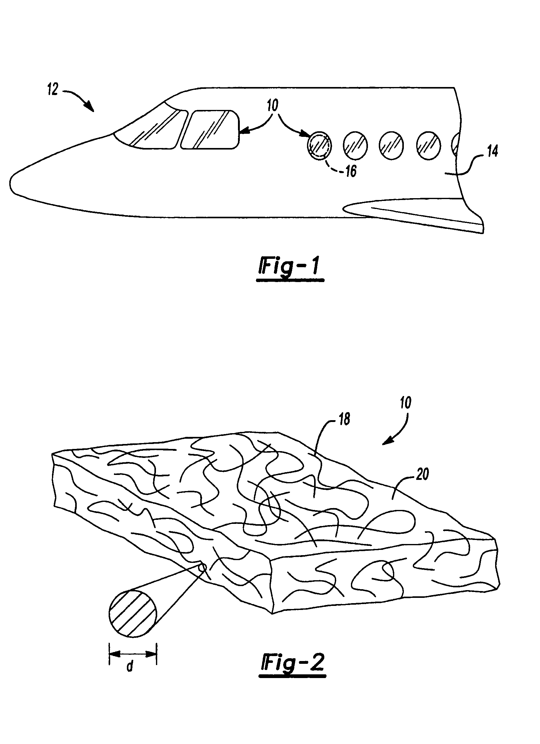
[0017] With reference to FIG. 1, a transparent nanofiber composite panel 10 constructed according to the principles of the present invention is shown in operative association with a mobile platform 12. More particularly, the transparent nanofiber composite panel 10 is an optical quality fiber reinforced transparency having high structural strength properties. Although the mobile platform 12 is shown as an aircraft, the mobile platform 12 could also be represented in the form of other mobile platforms, such as a ship, a train, a bus or an automobile. Additionally, although the present invention will be described below as particularly applicable for use in association with mobile platforms, the invention should not be so limited in application. It is envisioned that the invention is equally applicable to aircraft, tra...


PUM

PropertyMeasurementUnit
Temperatureaaaaaaaaaa
Lengthaaaaaaaaaa

Abstract

A transparent nanofiber composite panel that includes a plurality of transparent nanofibers integrated in random orientations within a transparent matrix is provided. The transparent nanofibers have a diameter that is less than the wavelength of visible light. The extremely small diameter of the transparent nanofibers allows the transparent panel to be substantially insensitive to an RI ‘mismatch’ between the transparent nanofibers and the transparent matrix. Additionally, due to random orientation of the transparent nanofibers within the transparent matrix the transparent nanofiber composite panel possesses substantially isotropic material properties such that the transparent nanofiber composite panel can be incorporated as a structural, load bearing, component of a larger structure.

Description

FIELD OF THE INVENTION [0001] The present invention relates to composite transparencies and more particularly to transparent composites utilized to provide transparent structural panels that can be incorporated into the structure of a mobile platform. BACKGROUND OF THE INVENTION [0002] Composite transparencies have many applications in many devices and structures. For example, composite transparencies can be utilized in eyeglasses, high security display cases, high-rise building windows and fighter jet cockpit canopies. In a particular instance, composite transparencies can be utilized to construct windows of a mobile platform such as an aircraft, train, bus, tank or ship. Generally, mobile platform windows formed of known transparent materials are not suitable for use as structural component of the mobile platform. In many instances, windows in many commercial mobile platforms are relatively small in size, due, at least in part, to the limited capabilities of current transparent wi...

Claims


Application Information

Patent Timeline
IPC IPC(8): D04H3/00
CPCB64C1/1484B82Y30/00Y02T50/433C08K2201/011C08K7/02Y10T428/249924Y02T50/40B29C45/0005B29C45/14073B29C45/14786B29C70/12B29C70/58C08K7/04C08K7/14
Inventor KOCH, WILLIAM J.NORDMAN, PAUL S.
Owner THE BOEING CO
Learn More