
Liquid fuel candle

a liquid fuel candle and candle body technology, applied in the field of candles, can solve the problems of difficult to decide whether or not deformation and consumption of the candle itself, and difficulty in deciding whether to light a conventional paraffin or other wax candle, etc., to achieve the effect of enhancing the overall burn time, and reducing the risk of burning

Inactive Publication Date: 2006-02-02
ENCHANTED MEADOW PRODS
View PDF6 Cites 9 Cited by
  • Summary
  • Abstract
  • Description
  • Claims
  • Application Information

AI Technical Summary

Benefits of technology

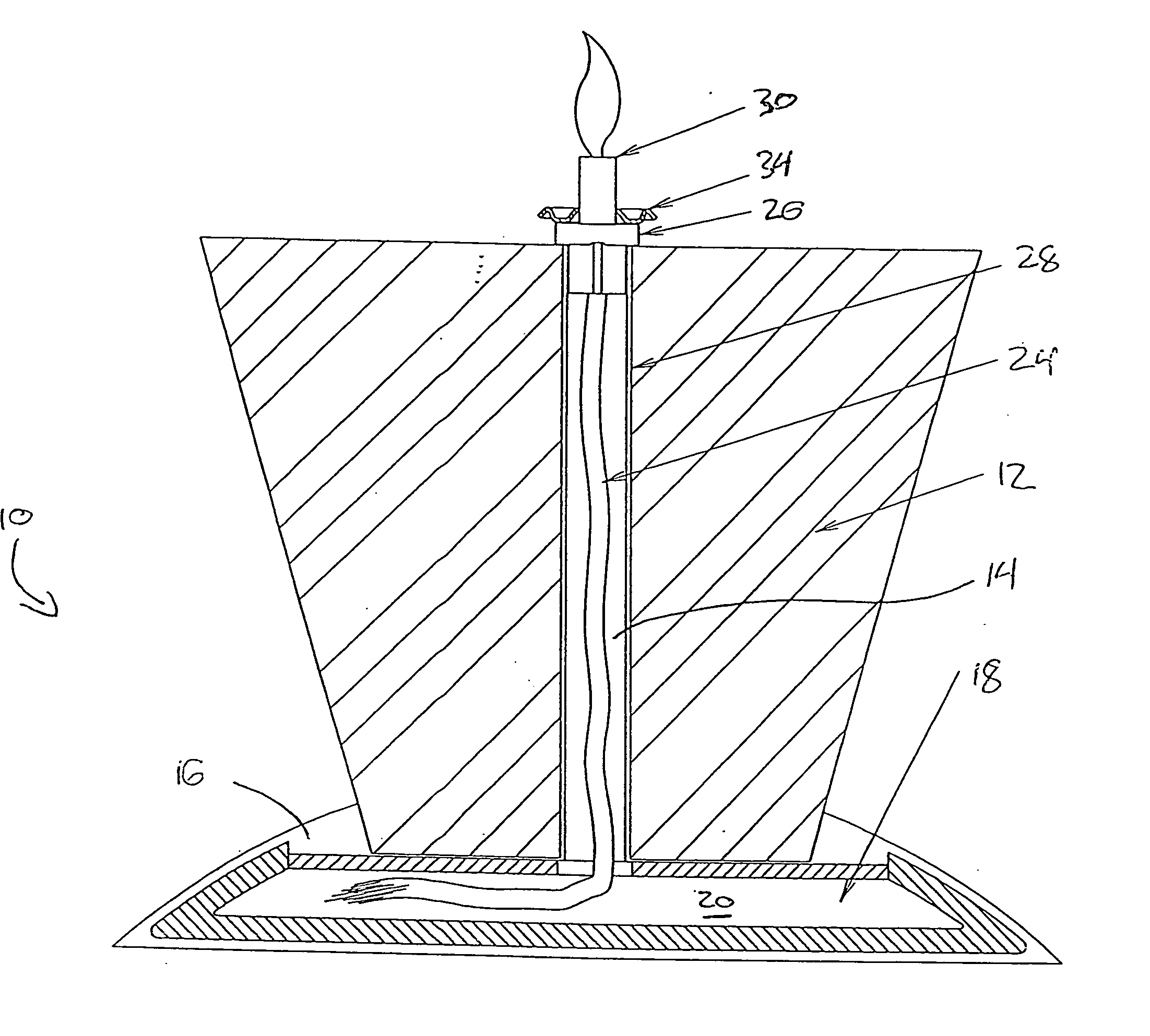
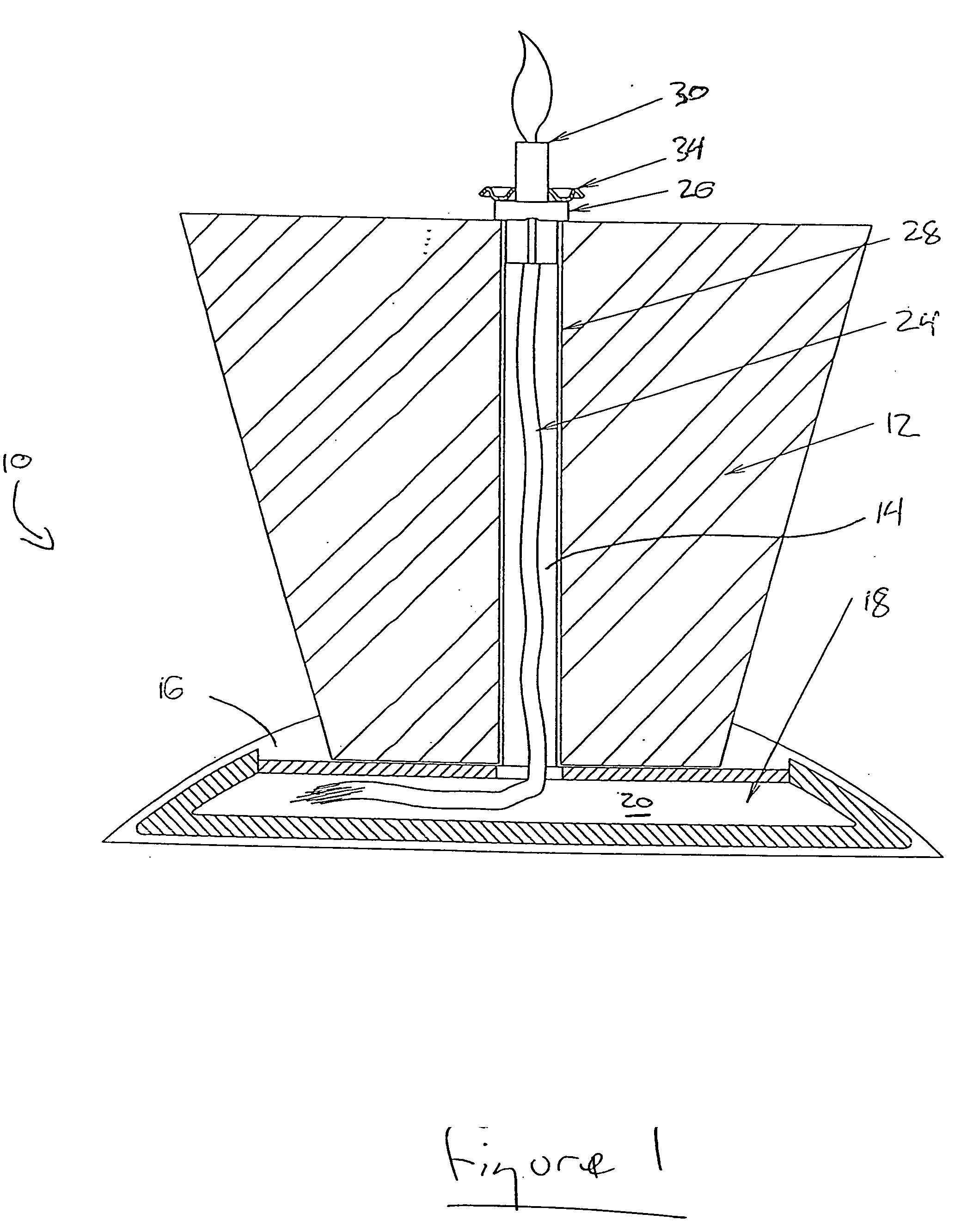
[0007] The liquid fuel is drawn by capillary action into the wick, and the insulator prevents the flame from liquefying or consuming the wax body when the second end of the wick is lit. Since the liquid fuel is stored within the reservoir provided by the associated base (and not within the wax body as in prior known liquid fuel candles), the wax body may be very slender and thin without compromising burn time. Overall burn time may also be enhanced relative to prior-known liquid fuel candles as the reservoir within the base can readily be made quite large without compromising the aesthetic qualities of the inventive liquid fuel candle.
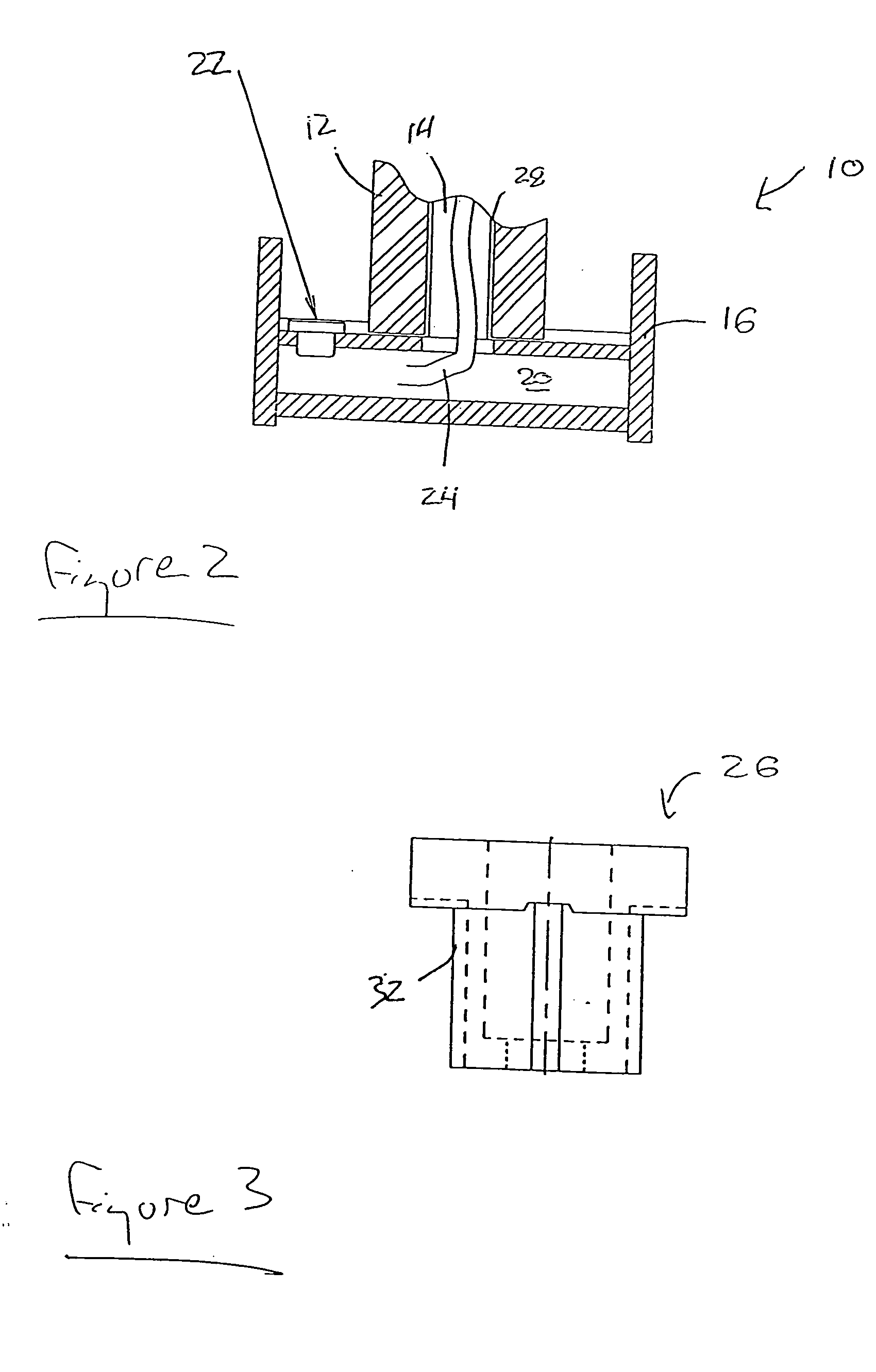
[0009] The insulator may preferably be constructed of a material having a high specific heat capacity in order to lessen the transfer of heat through to the wax body, and may in some embodiments include or be associated with a conduit formed of a separate heat resistant material (such as glass) surrounding the wick at or near its second end. In such embodiments, the interposition of the heat resistant conduit between the flame and the insulator avoids or lessens possible heat damage to the insulator during use of the liquid fuel candle. In some embodiments, the insulator also includes grooves or channels cut therethrough to permit air to communicate between the outside atmosphere and the liquid fuel reservoir to eliminate possible vapour lock.
[0010] In some embodiments, a diffuser ring or tray into which scented aromatherapy oils or the like may be placed (so as to diffuse into the air) may be affixed to or associated with the insulator. In use, the heat generated by the nearby flame accelerates the evaporation and dispersion of the scented oil.
[0011] The wick may be formed of fibreglass fibres or other suitable materials, and in some embodiments may be surrounded by a housing placed into the hollowed core of the wax body. Such wick housing may help prevent possible contamination of the wax body with the liquid fuel, and may also help to insulate the wax body from heat generated when the wick is lit.

Problems solved by technology

It is well known that the burning of conventional paraffin or other wax candles involves the liquefaction, deformation and consumption of the candle itself.
The expectation of such deformation and consumption may make it difficult to decide whether or not to light a conventional wax candle, particularly in the case of expensive ornamental candles.
Liquified wax also frequently runs down the sides of lit conventional wax candles, thereby creating a mess, and potentially damaging furniture or even constituting a fire hazard.
Although liquid fuel candles of the kind disclosed by Maclea may address the deformation and consumption issues inherent to conventional wax candles, it has been found that the placement of the liquid fuel reservoir within the core of such liquid fuel candles presents new difficulties.
In particular, the volumetric capacity of the internal fuel reservoir is necessarily limited relative to the size of such candles.
This limits the burn time of a given prior-known liquid fuel candle between refills, and also effectively precludes the creation of particularly slender liquid fuel candles of this sort.
Additionally, refilling the fuel reservoir of a liquid fuel candle of the sort disclosed by Maclea is messy and prone to spillage, and spilled liquid fuel may ruin the finish of the wax body of the candle or surrounding articles.

Method used


Image

  • Liquid fuel candle
  • Liquid fuel candle
  • Liquid fuel candle

Examples


Embodiment Construction

[0015] Referring to the Figures, the liquid fuel candle 10 comprises a wax body 12 defining a hollowed core 14. The wax body 12 is attached releasably or permanently to base 16 at one end of the wax body 12, and the base 16 is formed and dimensioned to resemble a conventional candle holder. Base 16 defines a reservoir 18 within which liquid fuel 20 may be stored, and also includes a re-sealable filling hole 22 in embodiments (as shown) where the wax body 12 and base 16 are permanently attached to one another.

[0016] A wick 24 preferably formed of fibreglass fibres is threaded through hollowed core 14 of wax body 12, and communicates at one end with liquid fuel 20 within base 16. At its second end, wick 24 projects slightly beyond the top of wax body 12, and is there situated within an insulator 26 that prevents wick 24 from contacting the outer surface of wax body 12. Housing 28 separates wick 24 from hollow core 14 of wax body 12 in order to avoid possible contamination of wax body...


PUM


Abstract

Provided is a liquid fuel candle comprising a wax body with a hollowed core, a base defining a reservoir for storage of liquid fuel attached to one end of the wax body, an insulator attached to the other end of the wax body, and a wick threaded through the hollowed core and communicating at one end with the liquid fuel and at the other end with the insulator. The base may be formed and dimensioned to resemble a conventional candle holder, and since the liquid fuel is stored within the reservoir provided by the base, the wax body may be very slender and thin without compromising candle burn time. A diffuser ring may be associated with the insulator for evaporation and dispersion of scented oils. More than one wax body, wick and insulator may be associated with a single base.

Description

FIELD OF THE INVENTION [0001] The present invention relates to candles, and in particular to reusable liquid fuel candles having a wax body that is not consumed during use. BACKGROUND OF THE INVENTION [0002] It is well known that the burning of conventional paraffin or other wax candles involves the liquefaction, deformation and consumption of the candle itself. The expectation of such deformation and consumption may make it difficult to decide whether or not to light a conventional wax candle, particularly in the case of expensive ornamental candles. Liquified wax also frequently runs down the sides of lit conventional wax candles, thereby creating a mess, and potentially damaging furniture or even constituting a fire hazard. It is, of course, also well known that conventional wax candles are normally secured on candle holders in order to ameliorate these latter hazards and disadvantages (and in many cases also to enhance the aesthetic appearance of the candle), but it nevertheless...

Claims


Application Information

Patent Timeline
IPC IPC(8): F23D3/18F23D3/16
CPCC11C5/006
Inventor RIVARD, DAVID M.
Owner ENCHANTED MEADOW PRODS
Learn More