Radiation emission control method, apparatus and program

a technology of radiation emission control and apparatus, applied in the field of radiation emission control methods, apparatus and programs, can solve the problems of detection errors, subject exposure to excessive radiation dosage, difficulty in holding breath at each respiratory phase of test subject, etc., and achieve the effect of minimizing radiation exposure to test subj

Inactive Publication Date: 2006-02-02
FUJIFILM HLDG CORP +1
View PDF4 Cites 17 Cited by
  • Summary
  • Abstract
  • Description
  • Claims
  • Application Information

AI Technical Summary

Benefits of technology

[0010] The present invention has been developed in view of the circumstances described above, and it is an object of the present invention to provide a radiation emission control method, apparatus and the program capable of de

Problems solved by technology

But, if the test subject is an individual having difficulties to communicate with the radiographer, such as an infant or the like, or when radiographs are to be imaged sequentially at each respiratory phase in order to obtain a dynamic image of the test subject under respiration, it may be difficult for the test subject to hold the breath at each of the respiratory phases.
The method that u

Method used


Image

  • Radiation emission control method, apparatus and program
  • Radiation emission control method, apparatus and program
  • Radiation emission control method, apparatus and program

Examples


Embodiment Construction

[0039] Hereinafter, embodiments of the present invention will be described in detail.

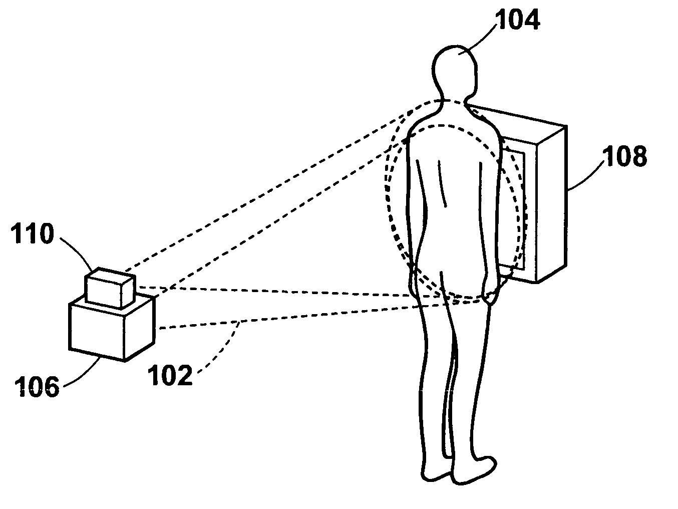
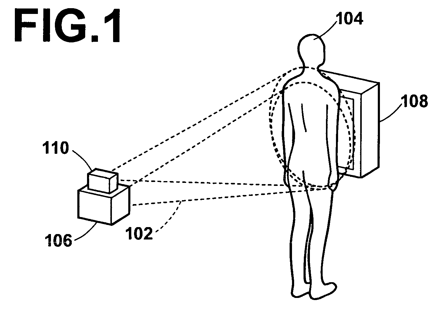
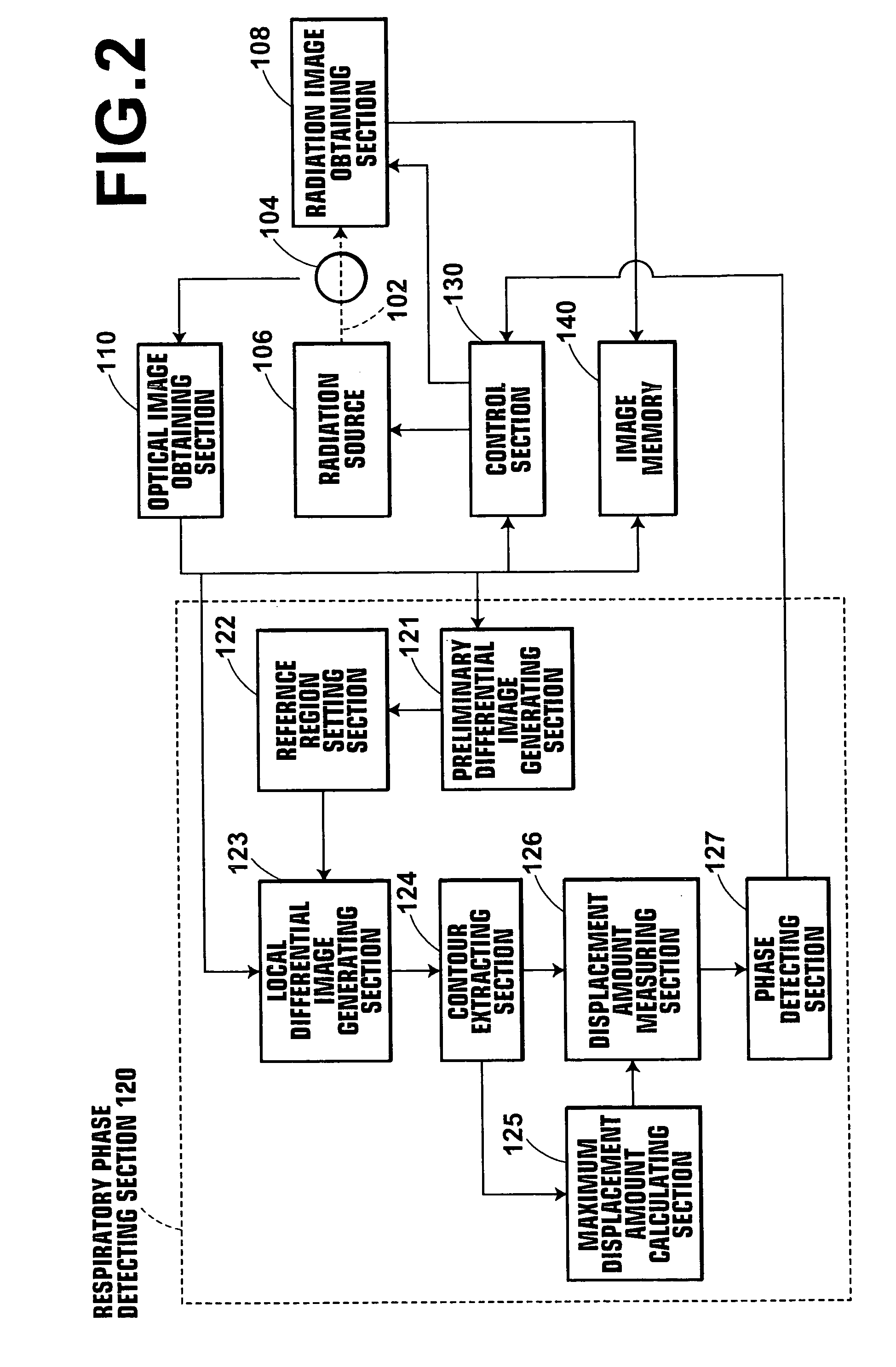
[0040]FIG. 1 is an external view of a radiographing system 100 illustrating one aspect of the external view thereof. FIG. 2 is a block diagram of the radiographing system 100 of the present invention illustrating one example of configuration thereof.

[0041] The radiographing system 100 comprises: a radiation source 106 for emitting radiation rays 102 to a test subject 104; a radiation image obtaining section 108 for obtaining radiation images P1 to Pm (m denotes an intended number of respiratory phases to be described later) of the test subject 104 by detecting radiation rays emitted from the radiation source and transmitted through the test subject 104; and an optical image obtaining section 110 for sequentially obtaining optical image Fi (i denotes an arbitrary frame number) of the test subject 104 having the contour that varies with respiration of the subject by imaging the subject continuously....


PUM


Abstract

A radiation emission control method, apparatus and the program capable of detecting respiratory phases of a test subject with constant accuracy and emitting radiation rays to the test subject in synchronization with an intended respiratory phase, while minimizing the radiation exposure to the subject. A test subject having a contour that varies with the respiration is optically imaged continuously by the optical image obtaining section to sequentially obtain optical images of the subject, and respiratory phases of the subject are detected simultaneously with the optical imaging by the respiratory phase detecting section based on the contour of the subject on the optical images. During the optical imaging, a radiation source is controlled by the control section such that radiation rays are emitted to the test subject when the detected respiratory phase corresponds to an intended respiratory phase of the subject.

Description

BACKGROUND OF THE INVENTION [0001] 1. Field of the Invention [0002] The present invention relates to a radiation emission control method, apparatus and the program. More specifically, the present invention relates to a radiation emission control method, apparatus and the program for obtaining a radiation image of a test subject when the subject is in an intended respiratory phase. [0003] 2. Description of the Related Art [0004] Generally, chest and abdominal radiographs, including digital images, are imaged or obtained as photographs for use to perform diagnostic image interpretations. Chest radiographs are often imaged when a patient as the test subject is in a maximum inhaled state to obtain a widest possible chest region for imaging, or they are imaged serially in each respiratory phase in order to observe the chest region under respiration. On the other hand, abdominal radiographs are often imaged when the test subject is in a maximum exhaled state to obtain a widest possible ab...

Claims


Application Information

Patent Timeline
IPC IPC(8): A61B5/05A61B5/08
CPCA61B5/0064A61B5/06A61B6/542A61B6/00A61B6/541A61B5/113
Inventor SENDAI, TOMONARI
Owner FUJIFILM HLDG CORP
Why Eureka
Try Eureka