Method and apparatus for reliable resynchronization of sequential decoders

a sequential decoder and resynchronization technology, applied in the field of sequential decoders, can solve the problems of non-negligent performance loss, complexity reduction, complexity increase, etc., and achieve the effect of reducing the complexity of an auxiliary map algorithm and avoiding erasur

Inactive Publication Date: 2006-02-02
IBM CORP
View PDF7 Cites 6 Cited by
  • Summary
  • Abstract
  • Description
  • Claims
  • Application Information

AI Technical Summary

Benefits of technology

[0017] It is another object of the invention to provide a system that reduces the complexity of an auxiliary MAP algorithm that determines an initial state for the resynchronization of the primary sequential decoding algorithm.
[0018] It is a further o...

Problems solved by technology

On one hand, a drawback of the maximum-likelihood and MAP decoders is that the complexity to implement such decoders grows exponentially with the number of encoder states.
In particular, an approximation of the a posteriori probabilities of the states and transitions in the decoder trellis diagram can be obtained at the end of the forward recursion of a reduced-state BCJR-type algorithm, with a substantial reduction of complexity, but such an approach would lead to a non negligible loss in performance.
On the other hand, sequential decoders present the drawback that the number of computations C required for the decoding process to advance by one branch in the decoder tree is a random variable having a Pareto distribution; in other words, the probability that the number of computations C is larger than N is given by the following equation:
Furthermore, as practical sequential decoders can perform only a finite number of operations in a given time interval, it is necessary to make provisions to avoid buffer overflow, which would have as a consequence incomplete decoding (erasures).
However, the BLA does not address satisfactorily the problem of possible errors in the resynchronization of the primary decoder.
In fact, using a hard-decision decoder as a secondary decoder yields a low reliability of the recovered state.
As a ...

Method used


Image

  • Method and apparatus for reliable resynchronization of sequential decoders
  • Method and apparatus for reliable resynchronization of sequential decoders

Examples


Embodiment Construction

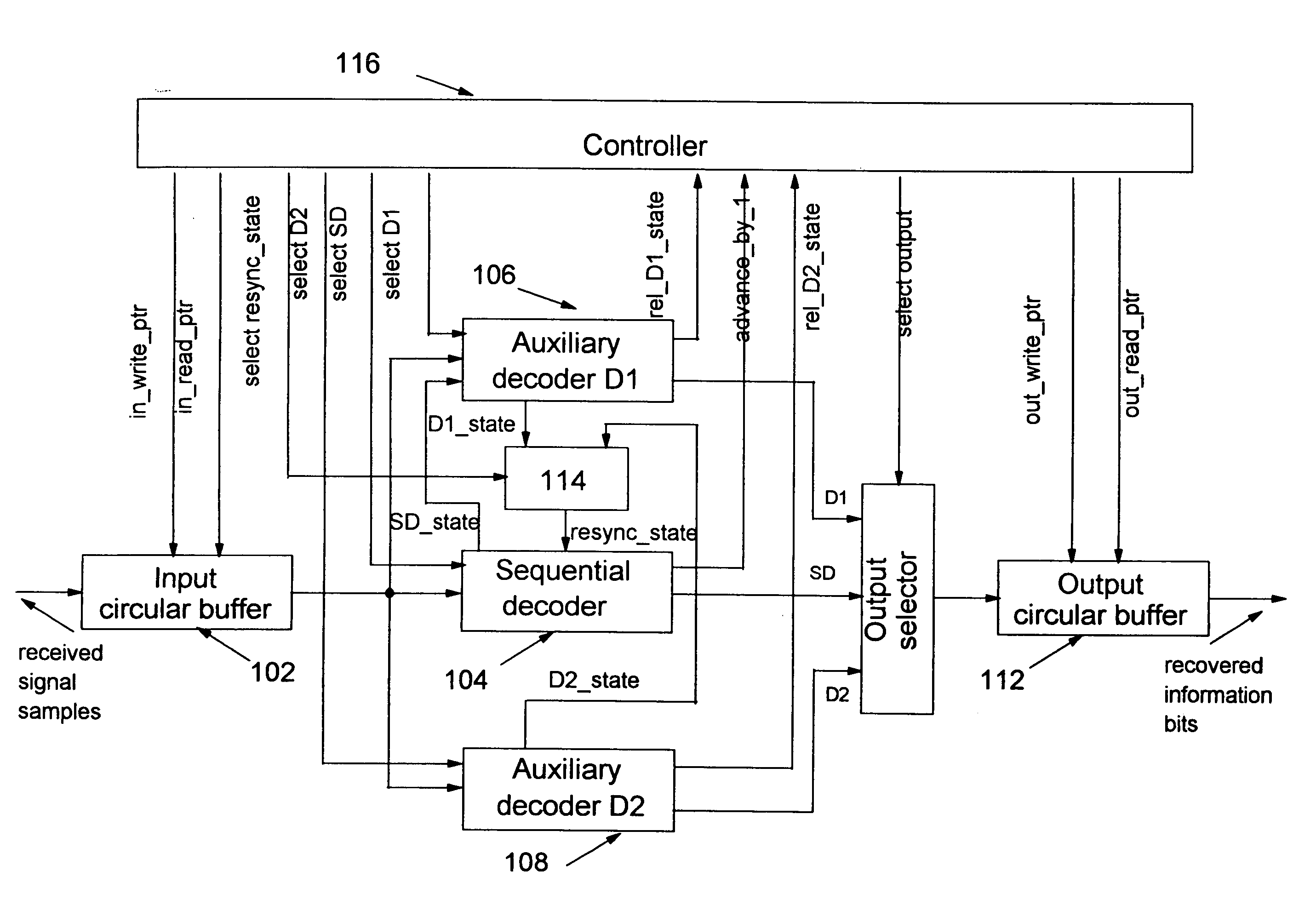
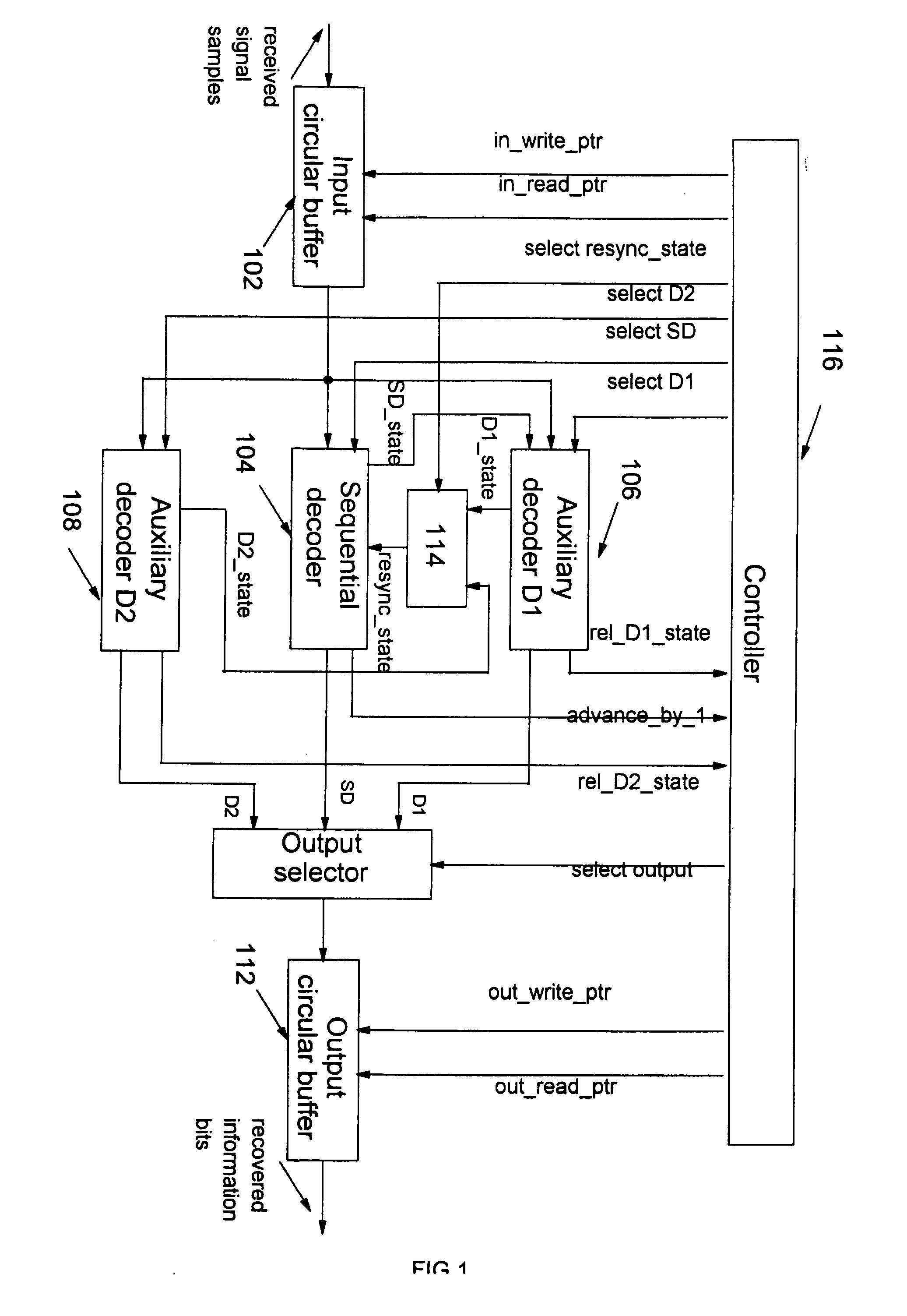
[0030] Referring first to FIG. 1, a block diagram of a preferred embodiment of the invention is described. Received signal samples are first input to a circular buffer 102, having Li memory locations. A sequential decoder 104 is connected to the input circular buffer by means of a signal samples line which is also input of a first auxiliary decoder 106 and of a second auxiliary decoder 108. The first and the second auxiliary decoders are preferably of the type reduced-state MAP decoders, but any general decoders that are able to provide a measure of the reliability of the state estimate could be used. One output of the sequential decoder (referenced SD on FIG. 1), of the first auxiliary decoder (referenced D1 on FIG. 1), and the second auxiliary decoder (referenced D2 on FIG. 1) are inputs of an output selector 110. The output selector is connected to an output circular buffer 112 to output the recovered information bits after the decoding process. A state selector 114 receives stat...


PUM


Abstract

A system and method for the resynchronization of a sequential decoder that decodes received signal samples stored within an input buffer is disclosed. The system comprises two auxiliary decoders coupled to the sequential decoder for running a simplified MAP decoding process when the input buffer reaches a threshold saturation level. Control of the respective increments of a read pointer and a write pointer allows one to detect the saturation of the input buffer and to derive a sequence of signal samples to the appropriate auxiliary decoder. The selected auxiliary decoder estimates a resynchronization state for the sequential decoder based on the sequence of signal samples. According to the read and the write pointers value, normal sequential decoding is resumed, otherwise, the second auxiliary decoder is selected. The selected auxiliary decoder estimates a resynchronization state for the sequential decoder based on a new sequence of signal samples.

Description

TECHNICAL FIELD [0001] The present invention relates to sequential decoders in general and in particular to a method and system for resynchronization of sequential decoders. BACKGROUND OF THE INVENTION [0002] Coding techniques are of fundamental importance for the reliable transmission of information over physical channels. The redundancy introduced by an encoder at the transmitter allows the decoder at the receiver to recover the sequence of information bits with a probability of error significantly smaller than that achieved by transmission systems that do not resort to coding techniques. An example of a technology that employs coding to achieve reliable data transmission is given by the contemporary Single-Pair High-Speed Digital Subscriber Line (SHDSL), for transmission at data rates of up to 2.32 Mbit / s over standard telephone lines in customer service areas. [0003] We usually distinguish two broad classes of coding techniques, each with several subclasses, one employing block ...

Claims


Application Information

Patent Timeline
IPC IPC(8): H03M13/03
CPCH03M13/3723H03M13/3977H03M13/3905
Inventor CHERUBINI, GIOVANNIWARE, MALCOLM
Owner IBM CORP
Why Eureka
Try Eureka