
Support system for a pilot nozzle of a turbine engine

a technology of support system and turbine engine, which is applied in the direction of fuel injecting pump, machine/engine, light and heating apparatus, etc., can solve the problem of the sleeves increasing in temperature relative to the support housing

Active Publication Date: 2006-02-09
SIEMENS ENERGY INC
View PDF19 Cites 41 Cited by
  • Summary
  • Abstract
  • Description
  • Claims
  • Application Information

AI Technical Summary

Benefits of technology

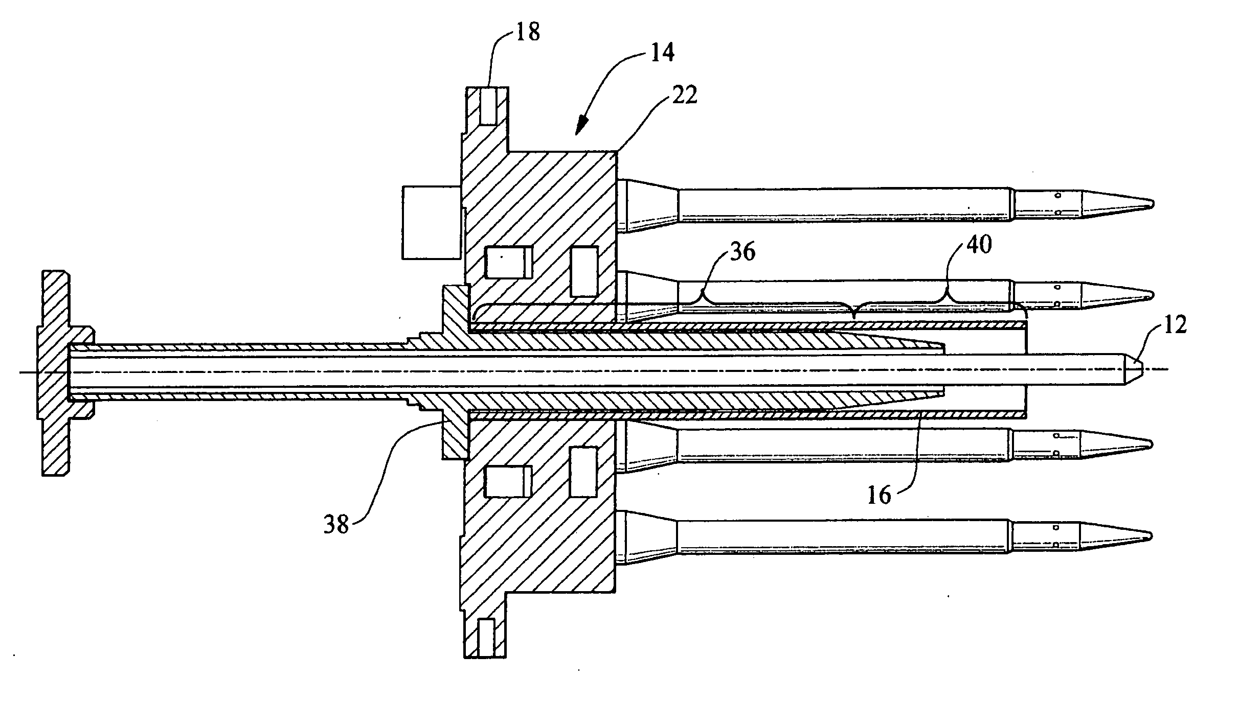
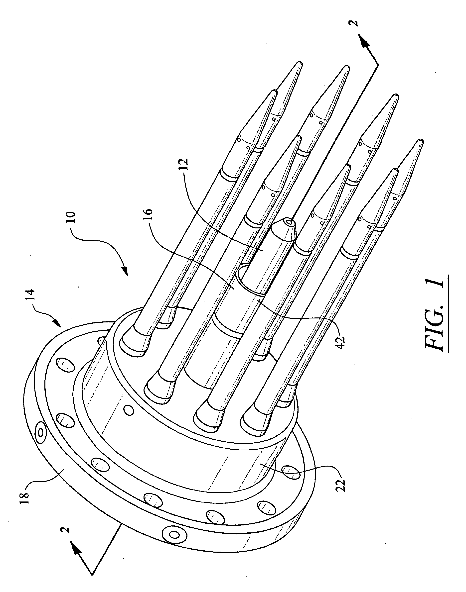
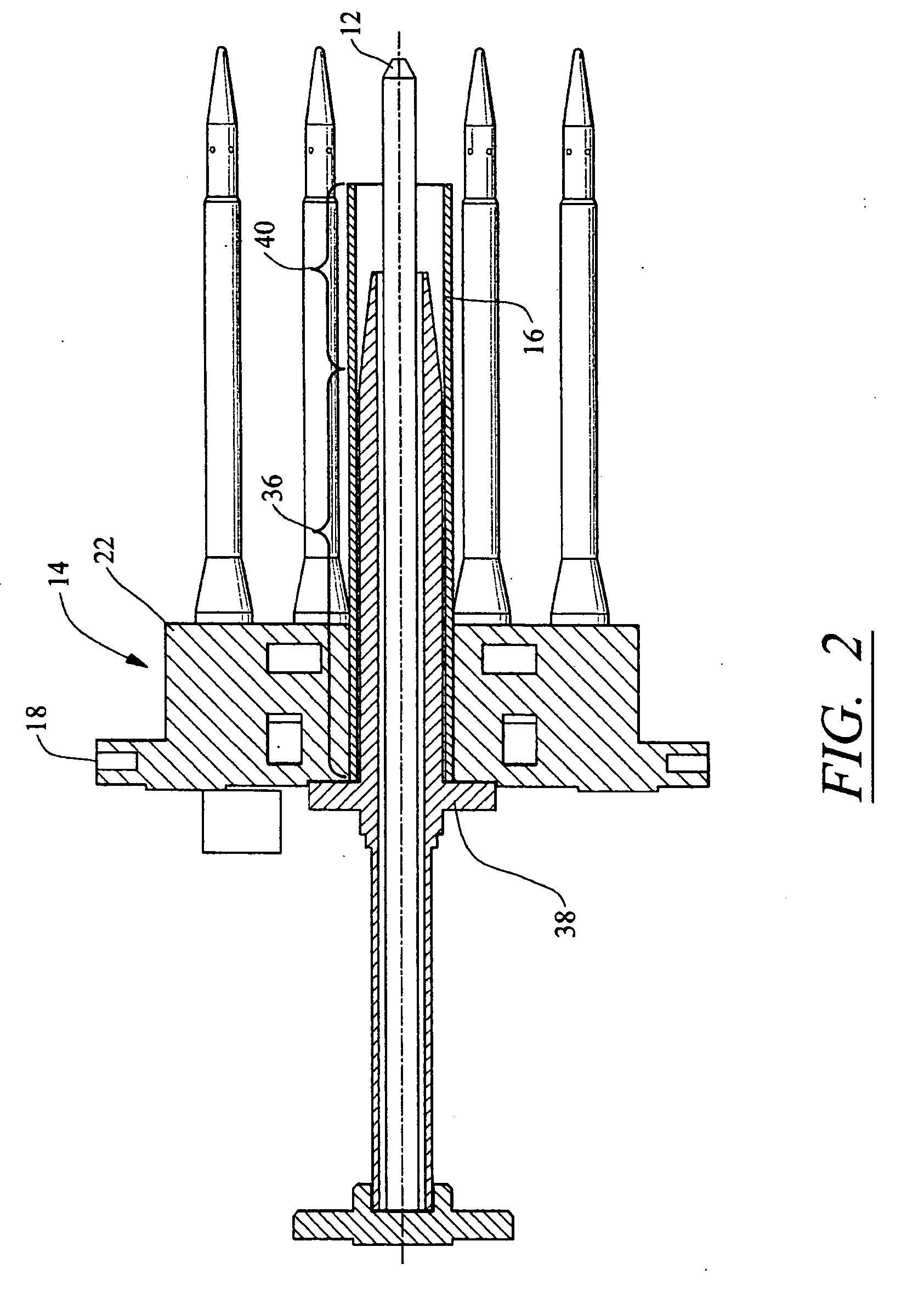
[0004] This invention relates to an automatic recovery pilot nozzle support system for a pilot nozzle of a fuel system of a turbine engine. The support system is configured to support a pilot nozzle with a sleeve and to increase the natural frequency of the pilot nozzle outside an excitation range to avoid destructive vibrations. The support system includes a sleeve that maintains contact with a support housing at substantially all times of operation of a turbine engine. Should the sleeve ever lose contact with the support housing during operation of a turbine engine, an insulative film of air may form between the sleeve and the support housing causing the sleeve to increase in temperature relative to the support housing. The sleeve, as a result, expands and regains contact with the support housing.
[0005] The support system may include a support housing having at least one orifice, a hollow sleeve positioned in the orifice of the support housing and having an outer diameter that is greater than an inner diameter of the orifice such that an interference fit exists between the support housing and the sleeve. The hollow sleeve may be adapted to receive a nozzle positioned in the hollow sleeve and generally aligned with the hollow sleeve. The hollow sleeve may also have first and second sections in which the first section may have a diameter that is greater than a diameter of the second section. The second section may be configured to contact and support a nozzle. The sleeve may also include a retention protrusion, which may be in the form of a ring and referred to as a collar, on an end of the sleeve for preventing the sleeve from being inserted completely through the support housing.
[0008] During operation, the support housing supports a pilot nozzle within a combustion chamber of a turbine engine. As the engine runs, the combustion chamber, and as a result, the support system and pilot nozzle, increase in temperature. As the sleeve of the support system increases in temperature and expands, the sleeve maintains contact with the support housing. Should the sleeve lose contact with the support housing, a film of insulative air may develop between the sleeve and the support housing causing the temperature of the sleeve to increase relative to the support housing. The increase in temperature of the sleeve causes the sleeve to expand and regain contact with the support housing.
[0009] An advantage of this invention is that the support system has an automatic support system configured such that should a sleeve of a pilot nozzle support system loose contact with a support housing, the sleeve will rapidly heat, expand, and regain contact with the support housing, thereby reestablishing an interference fit with, and the support of, the support housing.
[0010] Another advantage of this invention is the support system eliminates welds of conventional support systems that are typically exposed to extreme temperature gradients for attaching a sleeve of a pilot nozzle support system to a support housing.
[0011] Yet another advantage of this invention is the support system may be assembled in a time efficient manner with few assembly steps.

Problems solved by technology

Should the sleeve ever lose contact with the support housing during operation of a turbine engine, an insulative film of air may form between the sleeve and the support housing causing the sleeve to increase in temperature relative to the support housing.

Method used


Image

  • Support system for a pilot nozzle of a turbine engine
  • Support system for a pilot nozzle of a turbine engine
  • Support system for a pilot nozzle of a turbine engine

Examples


Embodiment Construction

[0018] This invention is directed to an automatic recovery pilot nozzle support system 10 usable in a turbine engine. As shown in FIGS. 1-4, the support system 10 enables a pilot nozzle 12 to be securely fastened to a support housing 14 of a turbine engine fuel system 16 throughout various engine operating loads and resulting thermal heating cycles. While the invention is directed to a support system for a pilot nozzle 12, the invention may also be used with other injector nozzles in a turbine engine and is not limited only to pilot nozzles. The support system 10 is configured such that during a natural heating cycle of a turbine engine during operation, the pilot nozzle is held by a sleeve 16 that maintains contact with the support housing 14 at substantially all times. In the event the sleeve 16 loses contact with the support housing 14, the thermal characteristics of the sleeve 16 cause the sleeve 16 to rapidly expand and regain contact with the support housing 14, thereby preven...


PUM


Abstract

An automatic recovery pilot nozzle support system for supporting a pilot nozzle in a fuel injection system of a turbine engine. The support system includes a sleeve extending from an orifice in a support housing, wherein the sleeve has a hollow opening for containing a pilot nozzle. The sleeve may increase the natural frequency of the pilot nozzle above an excitation zone, thereby limiting destructive vibrations. The sleeve may be attached to the support housing with an interference fit. The automatic recovery aspect of the support system enables the sleeve to maintain an interference fit with the support housing such that anytime the sleeve looses contact with the support housing, an insulative film of air forms between the sleeve and the support housing. The insulative film of air causes the temperature of the sleeve to increase, and the sleeve to expand and reform the interference fit with the support housing.

Description

FIELD OF THE INVENTION [0001] This invention is directed generally to turbine engines, and more particularly to pilot nozzle support systems of a turbine engine fuel assembly. BACKGROUND [0002] Typically, gas turbine engines include a compressor for compressing air, a combustor for mixing the compressed air with fuel and igniting the mixture, a fuel injection system, and a turbine blade assembly for producing power. Combustors often operate at high temperatures that may exceed 2,500 degrees Fahrenheit. Typical turbine combustor configurations expose components of turbine engine fuel systems to these high temperatures. Turbine engines fuel systems typically include pilot nozzles for injecting fuel into a combustion chamber. Conventionally, pilot nozzles have been bolted to a support housing to attach the pilot nozzles to turbine engines. A typical support housing consists of a base having an orifice extending through the base for receiving the pilot nozzle. The pilot nozzle is bolted...

Claims


Application Information

Patent Timeline
Patent Type & Authority Applications(United States)
IPC IPC(8): F02C7/22
CPCF23R3/283F23R2900/00017F23R3/343F23R3/286
Inventor MORAES, RICARDO FERREIRA
Owner SIEMENS ENERGY INC
Learn More