Eureka AIR delivers breakthrough ideas for toughest innovation challenges, trusted by R&D personnel around the world.

Ultraviolet emitting scintillators for oil detection

a technology of ultraviolet and scintillator, which is applied in the direction of conversion screens, instruments, nuclear engineering, etc., can solve the problems of poor light yield under gamma ray excitation, harsh use conditions, and inability to use scintillator materials

Inactive Publication Date: 2006-02-09
GENERAL ELECTRIC CO
View PDF8 Cites 18 Cited by
  • Summary
  • Abstract
  • Description
  • Claims
  • Application Information

AI Technical Summary

Problems solved by technology

The scintillator material may also desirably have high transparency in the ultraviolet range, which may be complicated by the number of materials which are opaque in this spectral range.
Known detectors utilize ultraviolet scintillator materials but have disadvantages which may prevent them from being used in harsh conditions.
In some instances, the scintillator materials' fluorescent decay times may be too long making the scintillator material impractical for use.
In other instances, light yield under gamma ray excitation may be poor.
Further, light yield may often decrease with increasing temperature.
Other scintillator materials' usable life spans may shorten when exposed to high temperatures, with light yield decreasing the longer that exposure to high temperatures continues.
Further complicating the choice of a scintillator material appropriate for harsh environments is the difficulty of predicting which materials will emit ultraviolet radiation in a range which overlaps a radiation detector which is also capable of operating in combination with the scintillator material in harsh, high temperature environments.
These and other drawbacks exist in known systems and techniques.

Method used


Image

  • Ultraviolet emitting scintillators for oil detection
  • Ultraviolet emitting scintillators for oil detection
  • Ultraviolet emitting scintillators for oil detection

Examples


Embodiment Construction

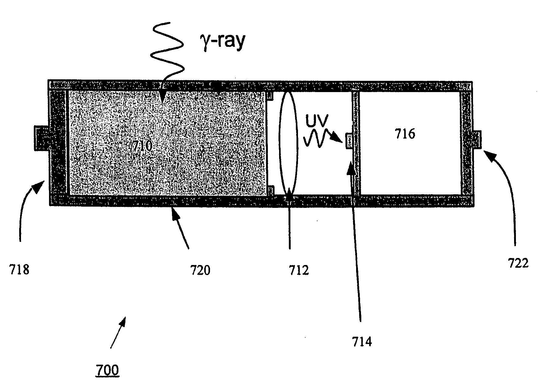
[0016] An aspect of the present invention is directed to ultraviolet-emitting scintillator materials for use in oil well drilling applications in harsh, down-hole environments where shock levels may be near 250 gravitational acceleration (G) and / or temperatures may approach or exceed 175° C. Another aspect of the invention is directed to an ultraviolet-emitting scintillator material coupled to a radiation detector.

[0017] The ultraviolet scintillator material according to exemplary embodiments of the present invention generally has a short decay time and little efficiency drop at elevated temperatures. The ultraviolet scintillator material comprises a cubic garnet host doped with an activator. The scintillator material may be a polycrystalline ceramic formed by sintering phosphors of the scintillator material. Alternatively, the scintillator material may be a single crystal formed from such known techniques as the Czochralski method. Light scattering within the cubic garnet host may...


PUM


Abstract

An aspect of the present invention is directed to a system for use in oil well drilling applications. The system includes a scintillator material having a cubic garnet host and praseodymium distributed within the host. The scintillator material emits ultraviolet radiation in response to stimulating gamma ray radiation. A radiation detector optically coupled to the scintillator detects the emitted ultraviolet radiation. Another aspect of the invention is a method for detecting oil. A radiation detector is optically coupled to a scintillator material having a cubic garnet host and praseodymium distributed within the host, wherein the praseodymium acts as an activator, and wherein the scintillator material emits ultraviolet radiation in response to stimulating gamma ray radiation. The detector and the scintillator material are lowered below the surface of the earth, and ultraviolet radiation emitted by the scintillator material in response to stimulating gamma ray radiation reflected by hydrogen bearing compounds indicating the presence of oil is detected by the detector.

Description

BACKGROUND OF THE INVENTION [0001] This invention relates generally to ultraviolet emitting scintillator materials and, more particularly, to an ultraviolet emitting scintillator material for use in environments such as oil well drilling applications. [0002] There is currently a need for gamma ray detection in the oil well drilling industry. High energy gamma rays reflected from Hydrogen (H) bearing compounds underground may indicate specific locations which may have oil. A scintillator material which has high ultraviolet luminescence when activated by gamma rays may be desirable for harsh, down-hole environments where shock levels may be near 250 gravitational acceleration (G) and temperatures may approach or exceed 175° Celsius (C.). [0003] For use in high temperature, harsh environments, the scintillator material may desirably have a number of characteristics. For example, it may be desirable to have a scintillator material which has a sufficient density to absorb as many gamma r...

Claims


Application Information

Patent Timeline
IPC IPC(8): G01V5/04
CPCC09K11/628C09K11/673C09K11/676C09K11/7719C09K11/772G21K4/00G01N23/22G01N33/2823G01N2223/1013G01N2223/505G01N2223/616C09K11/7774
Inventor SRIVASTAVA, ALOK MANICOMANZO, HOLLY ANNGRESKOVICH, CHARLES DAVID
Owner GENERAL ELECTRIC CO
Why Eureka
Eureka Blog
Learn More