The most essential and important issue in this development of EUVL systems is to develop ultra-low-expansion glasses as the basic substrate material suitable for optical systems and photomasks.
Even with the best grade among these glasses, the specification for the coefficient of thermal expansion stands at ±20 ppb / K (distribution in a glass
ingot; ±10 ppb / K), which is insufficient for the specification for ultra-low-expansion glass for EUVL systems of within ±5 ppb / K at the desired temperature.
These days, products using a
laser have been developed, but with the best products having an accuracy of ±5 ppb / K, this is insufficient.
Currently, development is being conducted with a target of ±1 ppb / K, but an improvement beyond this level cannot be expected.
In addition, the fact that this method requires specimens of a special shape (e.g. 100 mm (L)×6 mm φ), and the fact that, for the purpose of the measurements, destruction is entailed and surface distribution measurements with respect to actual specimens are impossible, etc., are problems from the point of view of materials evaluation methods and
quality control.
However, as for the method based on measurements of the
longitudinal wave velocity or the
refractive index, this accuracy can not be obtained unless big specimens having a thickness of 100 mm are used, and also, only an average value can be obtained in the thickness direction.
In this case, for the evaluation of specimens in which there exist periodic striae, which have developed into a problem in TiO2—SiO2 glass, it is impossible to obtain the distribution of thermal expansion coefficients corresponding to the periodicity of the striae.
Also, in order to measure longitudinal-
wave velocity, a measurement of the thickness of the specimen must also be performed, something which takes an unusual effort.
That is to say that a preparation method for an appropriate standard specimen with respect to materials with the possibility of having large acoustic losses and presenting
velocity dispersion has not been investigated.
Evaluation methods of the coefficient of thermal expansion based on conventional methods had the problems of having a low measurement accuracy, not being able to non-destructively evaluate specimen with shapes actually utilized, and not being able to measure distribution characteristics.
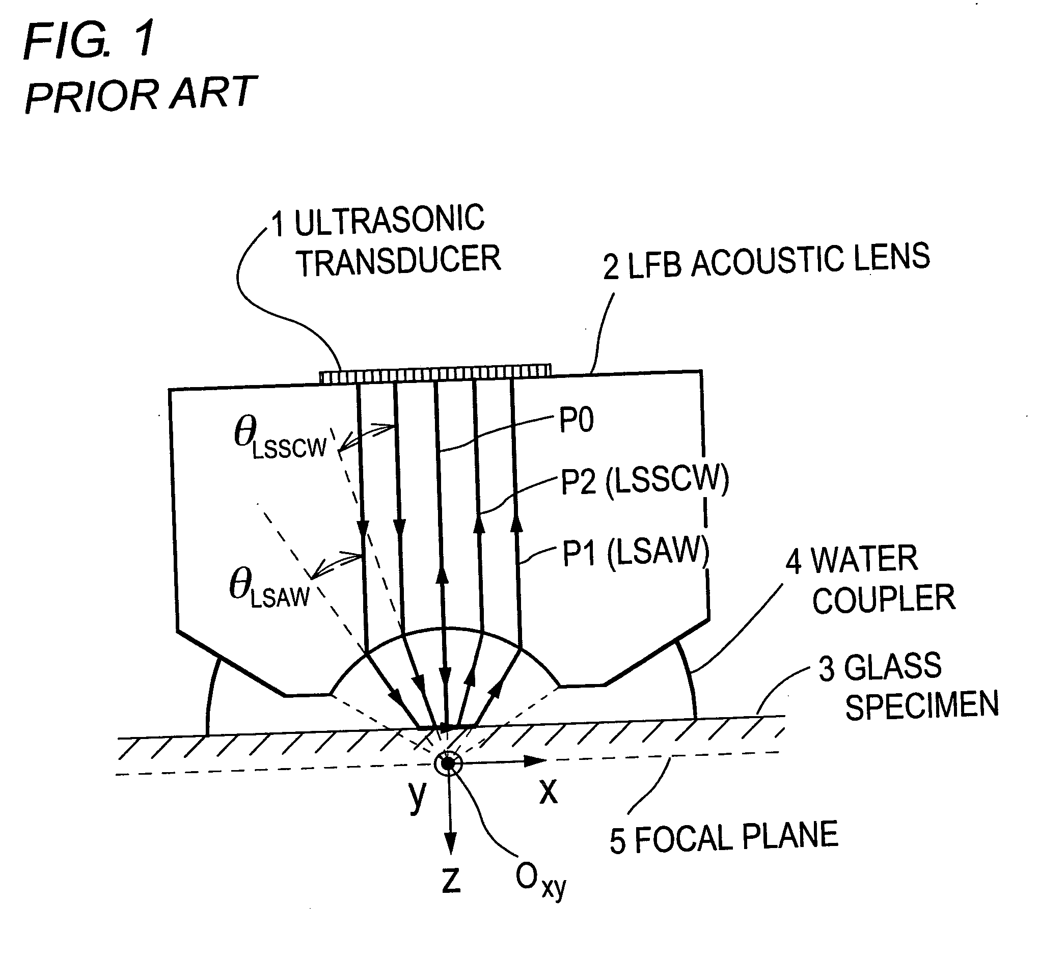
Moreover, as to materials evaluation based on an LFB ultrasonic material characterization
system, for which there can be expected a higher measurement accuracy than for conventional methods and the implementation, non-destructively and without contact, of measurements of the distribution characteristics in the surface of material substrates, an analytical method with respect to ultra-low-expansion glass materials having the possibility of exhibiting
velocity dispersion characteristics has not been developed.

