Method for the design of laminated composite materials

Inactive Publication Date: 2006-02-09
PECK SCOTT OWEN
View PDF9 Cites 38 Cited by
  • Summary
  • Abstract
  • Description
  • Claims
  • Application Information

AI Technical Summary

Benefits of technology

[0083] Design problems involving bending imply that the sequence of layers and materials within the composite material is important. Again, equating the linear invariant(s) of the specified laminated composite material with the linear invariant(s) of a laminate of candidate materials establishes the necessary conditions for feasibility of the laminate. Mathematically, the use of linear invariants separates the linear variables (ca

Problems solved by technology
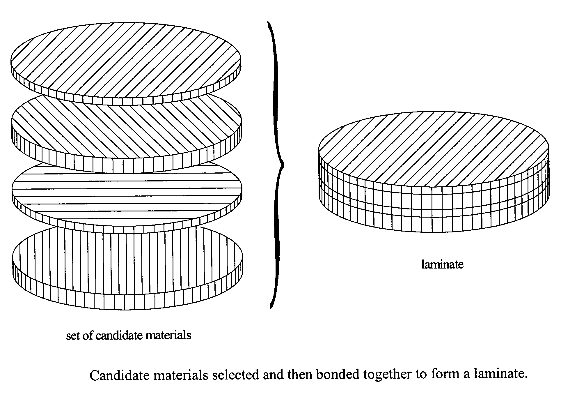
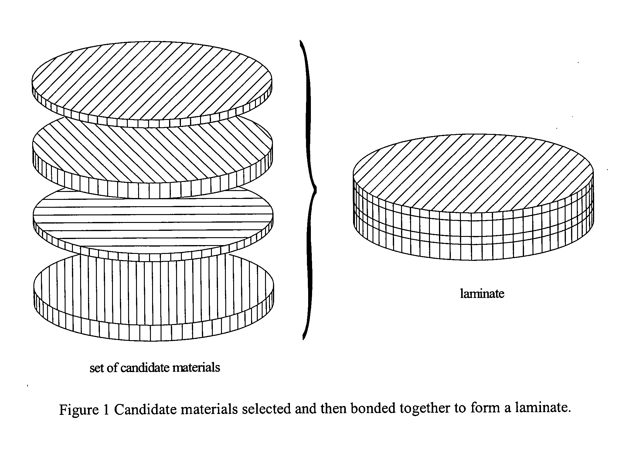
The design problem thus becomes one of choosing an optimal set of materials and associ

Method used


Image

  • Method for the design of laminated composite materials
  • Method for the design of laminated composite materials
  • Method for the design of laminated composite materials

Examples


numerical example

[0149] The objective is to design a laminate with the following specified stiffnesses: {D1111spec=8.27D1112spec=0D1122spec=0.19D1212spec=0.38D1222spec=0D2222spec=0.67}⁢GPa(8.5⁢.11)

[0150] Consider that three candidate materials with the following properties exist: T300{Q11111=181.8Q11121=0Q11221=2.90Q12121=7.17Q12221=0Q22221=10.35}⁢QPa⁢E⁢-⁢glass{Q11112=39.2Q11122=0Q11222=2.18Q12122=4.14Q12222=0Q22222=8.39}⁢GPa⁢Kevlar⁢-⁢49{Q11113=76.6Q11123=0Q11223=1.89Q12123=2.30Q12223=0Q22223=5.55}⁢GPa(8.5⁢.12)

[0151] Setting the two first invariants of the specification equal to the first invariants of the laminate yields 0.411+(z1z3)3-0.233⁢(z2z3)3=0⁢⁢0.402+(z1z3)3-0.2050⁢(z2z3)3=0(8.5⁢.13)

[0152] Equations (8.5.13) can be solved explicitly for the required normalized coordinates for a feasible solution. z1z3=-0.693⁢ ⁢z2z3=0.693(8.5⁢.14)

[0153] These coordinates imply that the respective volume fractions of the three layers are

v1=0.153 v2=0.693 v3=0.153  (8.5.15)

[0154] The normalized coordinate...


PUM

PropertyMeasurementUnit
Weightaaaaaaaaaa
Fractionaaaaaaaaaa
Thicknessaaaaaaaaaa

Abstract

The fundamental premise of designing structures with laminated composite materials is that the materials can be tailored to meet requirements by choosing the materials, thicknesses or thickness fractions, and orientation angles of constituent materials. Minimum weight, dimensional stability, natural frequency, and thermal conductivity are typical goals. This invention is NOT about the analysis of laminated materials and composites, of which there is no short supply. This invention is about the design of laminated materials, which has traditionally been an iterative event between the designer and the analysis tool. These iterations, if they occur at all, are often the most time consuming aspect of design. The fundamental premise of this invention is that tensor invariants of constituent material properties coupled with a tensor description of the specified material requirements can be used together to design laminated materials. The results of this invention can be used as a stand-alone design tool or as a value-added module in finite element codes. Specifically, by specifying material requirements, designers will use the method to select from a catalog of available materials a set that will satisfy their requirements. The designer is aided in the choice of materials, how much of each material to use, the layup angle orientation of the materials, and the sequencing of those materials in the composite laminate.

Description

STATEMENT REGARDING FEDERALLY SPONSORED RESEARCH OR DEVELOPMENT [0001] This invention is based in part on work performed under a Small Business Innovation Research contract between the Missile Defense Agency and Composite Design of Palo Alto, Calif. titled “Invariant Based Design of Laminated Composite Materials”, Contract DASG60-02-P-0130 (2002).REFERENCES CITED U.S. Patent [0002] 1. R. P. Reese, T. W. Gossard, Jr., “Near Zero CTE Carbon Fiber Hybrid Laminate,” U.S. Pat. No. 5,993,934, Nov. 30, 1999. [0003] 2. Vasey-Glandon et al., Knowledge Driven Composite Design Optimization Process and System Therefore, U.S. Pat. No. 6,341,261, Jan. 22, 2002. [0004] 3. Vasey-Glandon et al., Knowledge Driven Composite Design Optimization Process and System Therefore, U.S. Pat. No. 5,984,511, Nov. 16, 1999. [0005] 4. Ward, et al., Method and Apparatus for the Design and Construction of Composite Parts, U.S. Pat. No. 5,006,990, Apr. 9, 1991. [0006] 5. Ward, et al., Method for the Design and Const...

Claims


Application Information

Patent Timeline
IPC IPC(8): B32B5/12
CPCB32B37/00G06F2217/80G06F2217/44G06F17/50G06F30/00G06F2113/26G06F2119/08Y10T428/31504
Inventor PECK, SCOTT OWEN
Owner PECK SCOTT OWEN
Why Eureka
Try Eureka