Integrated metrology systems and information and control apparatus for interaction with integrated metrology systems

a metrology system and information control technology, applied in the field of integrated metrology systems, can solve the problems of subscribers not knowing how much it costs to operate a given appliance, inability to accurately and efficiently determine how much of each utility commodity the subscriber, and the supply of utility commodity suppliers, so as to achieve positive economic advantages, reduce operating expenses, and improve control ability

Active Publication Date: 2006-02-09
ENERGYCITE INC
View PDF13 Cites 217 Cited by
  • Summary
  • Abstract
  • Description
  • Claims
  • Application Information

AI Technical Summary

Benefits of technology

[0009] Advances in microelectronics and communications technology render known practices for utility metering, utility meter reading, and subscriber billing obsolete. It now is possible to provide the subscriber up-to-the-second, real-time and accumulated energy usage and pricing information, to provide means to control such usage, and to automatically transfer this information to multiple utility commodity suppliers. The same technology provides the utility commodity suppliers significant positive economic advantages based on new control ability, reduced operating expenses, and new revenue streams resulting from new value added products and services. Further, new financing alternatives may be created which reduce or eliminate the necessity of the utility commodity supplier having to pay for the acquisition costs associated with the new metering equipment. Use of this technology may allow utility commodity suppliers to reduce costs and increase efficiency, thereby, enhancing profitability, in the delivery of utility commodities to subscribers.
[0014] Yet a further need has arisen for a system including a LAN node or gateway. It is a feature of such systems that the meter may be the principal node or gateway in a subscriber's wireless LAN, such that the meter may receive data from and transmit data to other utility meters. In addition, the subscriber's LAN gateway may be an interface to a subscriber's information and control apparatus, as well as an in-home appliance and load monitoring and control network. It is an advantage of such meters that they may include sufficient data logging and processing hardware and embedded firmware to allow for the implementation of the same type of variable rate structures described above with respect to electrical utility commodity service, for gas and water utility commodity service. While the need for this capability may not be immediately apparent, this feature enables variable rate implementation, such as time-of-use (TOU), peak demand, day-of-use, rate structures, for gas and water utility commodity services.
[0017] Yet another need has arisen for a system adapted to be responsive to product life cycle, mean time between failures (MTBF), and environmental considerations. It is a feature of such systems that the utility meters may be constructed to ensure a 20-year life cycle, a MTBF consistent with known electro-mechanical utility meters, and continuous operation at temperatures ranging between about −40° C. and about +85° C. Preferably, the electronic and mechanical components may allow for extended operation in sea coast areas with relatively high air concentrations of sodium chloride and other salts and may be immune from transient power events consistent with ANSI C-12.11, which standard is incorporated herein by reference, and other relevant specifications.

Problems solved by technology

A fundamental problem faced by utility commodity uses in controlling their use of such utility commodities is that it is difficult to determine accurately and efficiently how much of each utility commodity the subscriber has used and is using and, therefore, how much the subscriber has spent and is spending on utility commodities at any point in time.
Further, because utility commodity rates may vary over time and by time of use, subscribers may not know how much it costs to operate a given appliance, maintain a certain household temperature, water the lawn, or the like.
Utility commodity suppliers (e.g., public utility companies) also are largely unable to determine how much of a utility commodity a subscriber is using at any point in time.
Such utility commodity suppliers largely are unable to determine what the maximum or peak amount of a utility commodity has been or is being used by an individual subscriber nor are they able to develop a correlation between time of utility commodity use or the amount used.
As a result of these metering limitations, subscribers may not receive or may not be able to receive the benefit of flexible pricing options that more closely match their individual usage profiles.
This practice represents a significant cost in time and personnel to the utility commodity suppliers and, ultimately, to the subscribers.
Moreover, because the utility meter readers often must enter the subscriber's property to read the utility meter, such practices also raise non-trivial, liability issues for the utility commodity suppliers and security issues for the subscribers.

Method used


Image

  • Integrated metrology systems and information and control apparatus for interaction with integrated metrology systems
  • Integrated metrology systems and information and control apparatus for interaction with integrated metrology systems
  • Integrated metrology systems and information and control apparatus for interaction with integrated metrology systems

Examples


examples

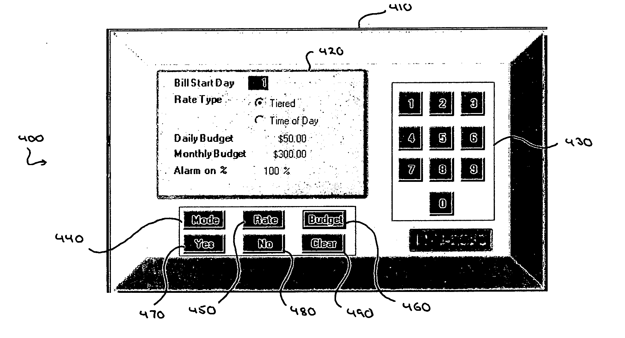
[0081] The invention will be further clarified by a consideration of the following examples, which are intended to be purely exemplary of the use of the invention. Referring to FIG. 7, the subscriber's information and control apparatus product is comprised of hardware and software components. The subscriber's information and control apparatus may comprise of a wireless, data collection interface, a CPU, and power supply, Graphical User Interface (GUI), an optional cradle for battery operation, and twelve (12) key alphanumeric key pads for data entry and on four (4) directional keys for on-screen navigation. The hardware is portable, so that the subscriber may move about his or her location in order to see the affect of turning on and off power to appliances has on usage costs.

[0082] The software, which is ideally downloadable to the hardware, consists of data collection, data computation, storage and GUI functionality. The software also supports clock set, on-demand use rate inform...


PUM


Abstract

A system is disposed at a location of a utility commodity subscriber for informing the subscriber of utility commodity cost and usage and for controlling utility commodity usage. The system includes one or more utility meters, an information and control apparatus, a first data communication link, and a second data communication link. The one or more meters measure usage of one or more utility commodity and for generating one or more usage signals including a measurement of the subscriber's usage of the one or more utility commodities. The information and control apparatus includes a microprocessor, a memory, a clock, and a user interface, for inputting and outputting information. The first data communication link is between the one or more utility meters and the information and control apparatus and provides the one or more usage signals to said information and control apparatus for storage in the memory. The second data communication link is between the information and control apparatus and one or more central locations associated with the one or more utility commodity. The second communication link also provides rate information related to usage of the one or more utility commodity from the one or more central location to the information and control apparatus and provides utility commodity usage data from the information and control apparatus to the one or more central location. The microprocessor computes an accumulated cost of one or more utility commodity for a predetermined period of time according to the clock, the one or more usage signal, and the rate information. Information related to the accumulated cost is provided to the user interface for output to the subscriber.

Description

[0001] This application claims the benefit of U.S. Provisional Patent Application No. 60 / 598,755, filed Aug. 3, 2004, which is incorporated herein by reference.BACKGROUND OF THE INVENTION [0002] 1. Field of the Invention [0003] The present invention relates to integrated metrology systems comprising at least one utility meter, an information and control apparatus, a first data communication link, and a second data communication link. Further, the invention relates to information and control apparatus comprising an information and control panel and an interface for interaction with integrated metrology systems. Such systems and apparatus allow subscribers to budget, monitor, and manage their expenditures for utility commodities and to control their use of utility commodities through local or remote interfaces. [0004] 2. Description of Related Art [0005] As utility commodity (e.g., natural gas, propane, heating oil, electricity, water, sewer, and the like) prices rise, increasing numb...

Claims


Application Information

Patent Timeline
Patent Type & Authority Applications(United States)
IPC IPC(8): G01R21/133
CPCG01D4/004G01R21/133Y04S20/322H04M11/002Y02B90/242G06Q50/06Y02B90/20Y04S20/30
Inventor TAMARKIN, TOMER D.BLOCK, ROBERT S.FINE, PHILLIP M.
Owner ENERGYCITE INC
Why Eureka
Try Eureka