Foreign object damage tolerant nacelle anti-icing system

a technology of anti-icing system and nacelle, which is applied in the direction of de-icing equipment, ground installations, aircraft power plants, etc., can solve the problems of reducing the overall engine efficiency, electrical systems, etc., and achieves sufficient impact energy resilience, prevent ice buildup, and thermal conductivity sufficient

Inactive Publication Date: 2006-02-16
PRATT & WHITNEY CANADA CORP
View PDF27 Cites 37 Cited by
  • Summary
  • Abstract
  • Description
  • Claims
  • Application Information

AI Technical Summary

Benefits of technology

[0004] Therefore, in accordance with the present invention, there is provided a nacelle for housing a gas turbine engine, the nacelle comprising: an inlet lip defining a leading edge of the nacelle; a conduit located within the inlet lip, the conduit having a fluid circulating therein, the fluid providing a heat source; and an energy attenuating member located within the inlet lip and disposed between the leading edge and the conduit, the energy attenuating member providing protection to the conduit from foreign object damage and being thermally conductive such that heat transfer communication between the conduit and the leading edge is provided.
[0005] Also in accordance with the present invention, there is provided a system for preventing ice build up on an inlet lip of a nacelle housing a gas turbine engine, the system comprising: a cavity extending within the inlet lip and partly defined by a leading edge thereof; first means for providing a fluid circulation within the cavity; a hot fluid circulating within the first means; and second means for providing heat transfer communication between the first means and the leading edge and for providing foreign damage protection to the first means, the second means filling a free space between the first means and the leading edge.
[0006] Further in accordance with the present invention, there is provided a method of producing a foreign object damage tolerant anti-icing system for an inlet lip of a nacelle housing a gas turbine engine, the method comprising the steps of: defining a circumferential passage within the inlet lip; defining a free space between the circumferential passage and a leading edge of the inlet lip; filling the free space with a material, the material having sufficient thermal conductivity to enable heat transfer communication between the circumferential passage and the leading edge and having sufficient impact energy resilience to protect the circumferential passage from foreign object damage; and connecting the circumferential passage to a system circulating a hot fluid, the hot fluid circulating through the circumferential passage being adapted to provide heat to the inlet lip through the circumferential passage and the material.
[0007] There is further provided, in accordance with the present invention, a method of preventing foreign object damage to an anti-icing system in an inlet of a nacelle for housing a gas turbine engine, the method comprising: providing a conduit defining a fluid passage within the inlet lip; defining a space between the conduit and a leading edge of the inlet lip, and disposing an energy attenuating member within the space; enabling heat transfer communication between the conduit and an outer surface of the inlet lip via the energy attenuating member; and circulating a hot fluid within the conduit.

Problems solved by technology

However, using bleed from the engine core reduces overall engine efficiency and electrical systems draw electrical power which impose a non-propulsive load on the engine.

Method used


Image

  • Foreign object damage tolerant nacelle anti-icing system
  • Foreign object damage tolerant nacelle anti-icing system
  • Foreign object damage tolerant nacelle anti-icing system

Examples


Embodiment Construction

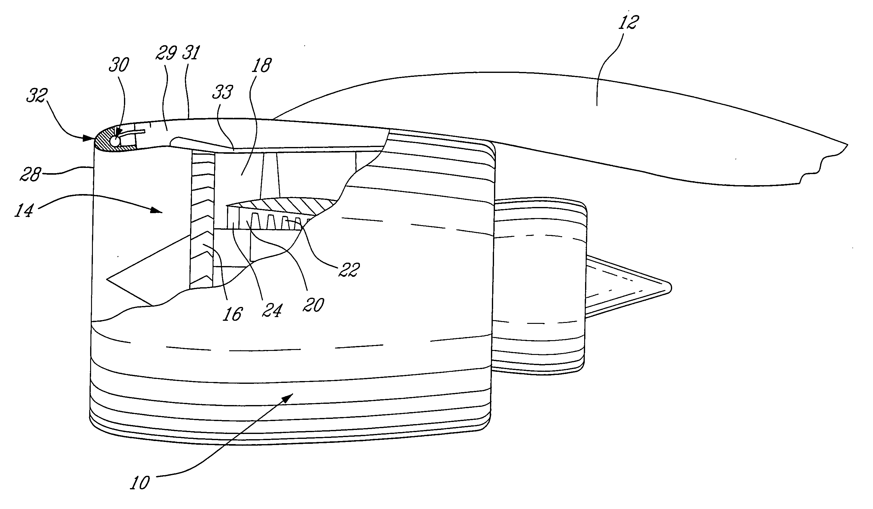
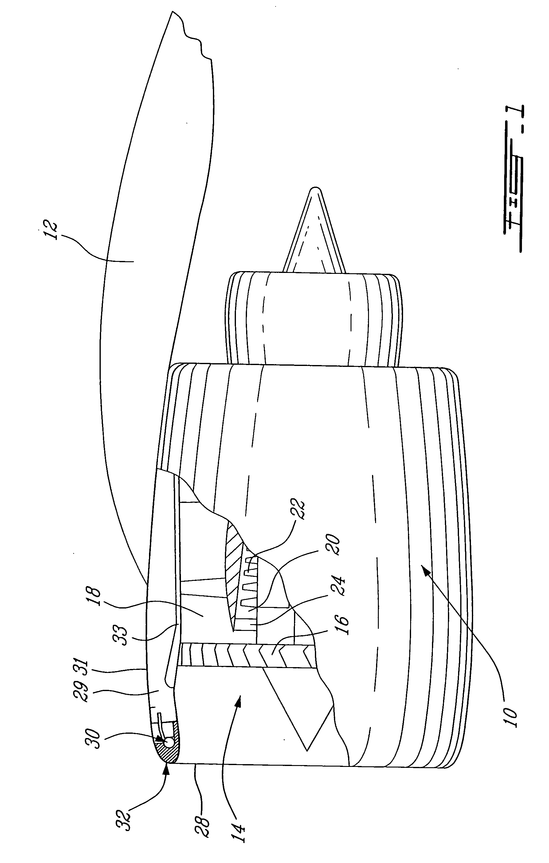
[0012] Referring to FIG. 1, a nacelle 10 of an aircraft power plant 14 is fixed to a mounting structure 12 of an aircraft. The power plant 14 will be preferably described herein as a gas turbine engine, and more particularly as a turbofan, however the nacelle inlet lip anti-icing and oil cooling system of the present invention can be used with any suitable aircraft power plant. The turbofan engine 14, as illustrated in FIG. 1, shows an upstream fan 16 that provides initial compression of the engine inlet airflow which is subsequently split into an outer annular bypass airflow passage 18 and an inner annular engine core airflow passage 20. Generally, inlet guide vanes 24 are disposed at least within the engine core airflow passage 20, upstream of a following compressor stage 22.

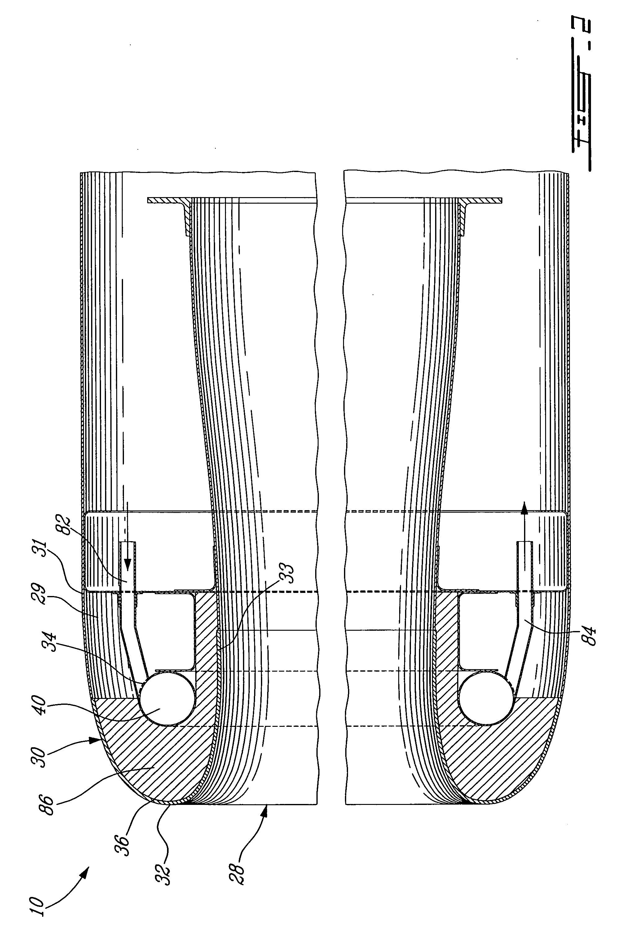
[0013] The nacelle 10 is generally tubular, having an outer surface 31 and an inner surface 33 substantially parallel to one another and radially spaced apart to define a hollow cavity 29 therebetween. The ci...


PUM


Abstract

A nacelle for housing a gas turbine engine is disclosed. The nacelle comprises an inlet lip defining a leading edge of the nacelle and a conduit located within the inlet lip, the conduit having a fluid circulating therein. The fluid provides a heat source. An energy attenuating member is located within the inlet lip between the leading edge and the conduit. The energy attenuating member provides protection to the conduit from foreign object damage and is thermally conductive such that heat transfer communication between the conduit and the leading edge is provided.

Description

TECHNICAL FIELD [0001] The present invention relates to de-icing and anti-icing systems for use with nacelles housing aircraft engines. BACKGROUND OF THE INVENTION [0002] Turbofan nacelles typically require inlet de-icing for safety reasons. Prior art engine inlet anti-icing systems commonly employ a thermal source, such as hot air bled from the engine core or an electrical heating element, for providing heat to remove ice build-up on the inlet surfaces. However, using bleed from the engine core reduces overall engine efficiency and electrical systems draw electrical power which impose a non-propulsive load on the engine. Opportunities for improvement therefore exist. SUMMARY OF INVENTION [0003] It is therefore an aim of the present invention to provide an improved anti-icing system for an aircraft engine nacelle. [0004] Therefore, in accordance with the present invention, there is provided a nacelle for housing a gas turbine engine, the nacelle comprising: an inlet lip defining a l...

Claims


Application Information

Patent Timeline
Patent Type & Authority Applications(United States)
IPC IPC(8): B64D15/16
CPCB64D2033/0233B64D15/04
Inventor BRAND, JOSEPH HORACESAVAGE, WILLIAM JOHN KIRBY
Owner PRATT & WHITNEY CANADA CORP
Why Eureka
Try Eureka