Method for controlling the firing angle of an electric motor
- Summary
- Abstract
- Description
- Claims
- Application Information
AI Technical Summary
Benefits of technology
Problems solved by technology
Method used
Image
Examples
Embodiment Construction
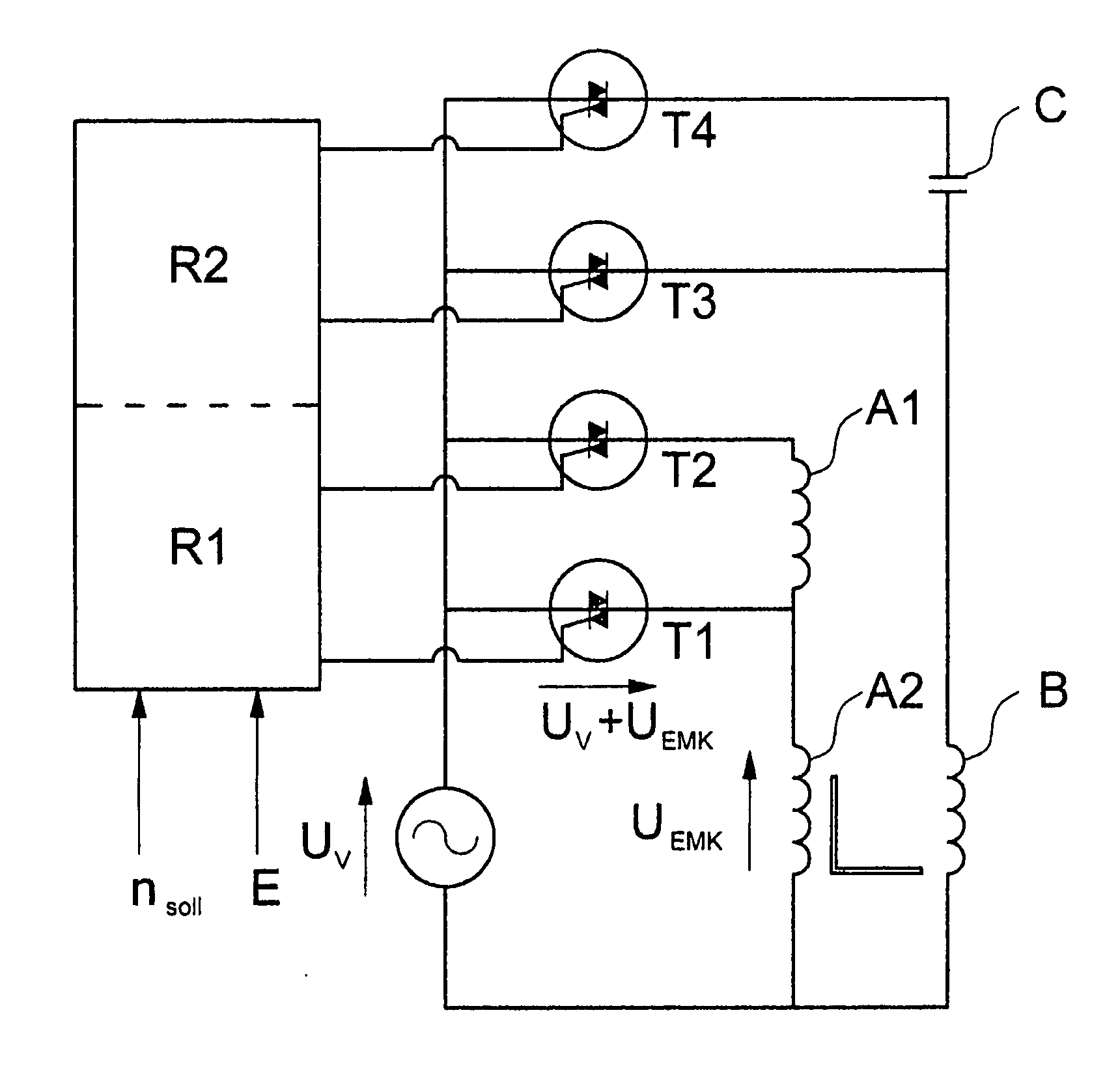
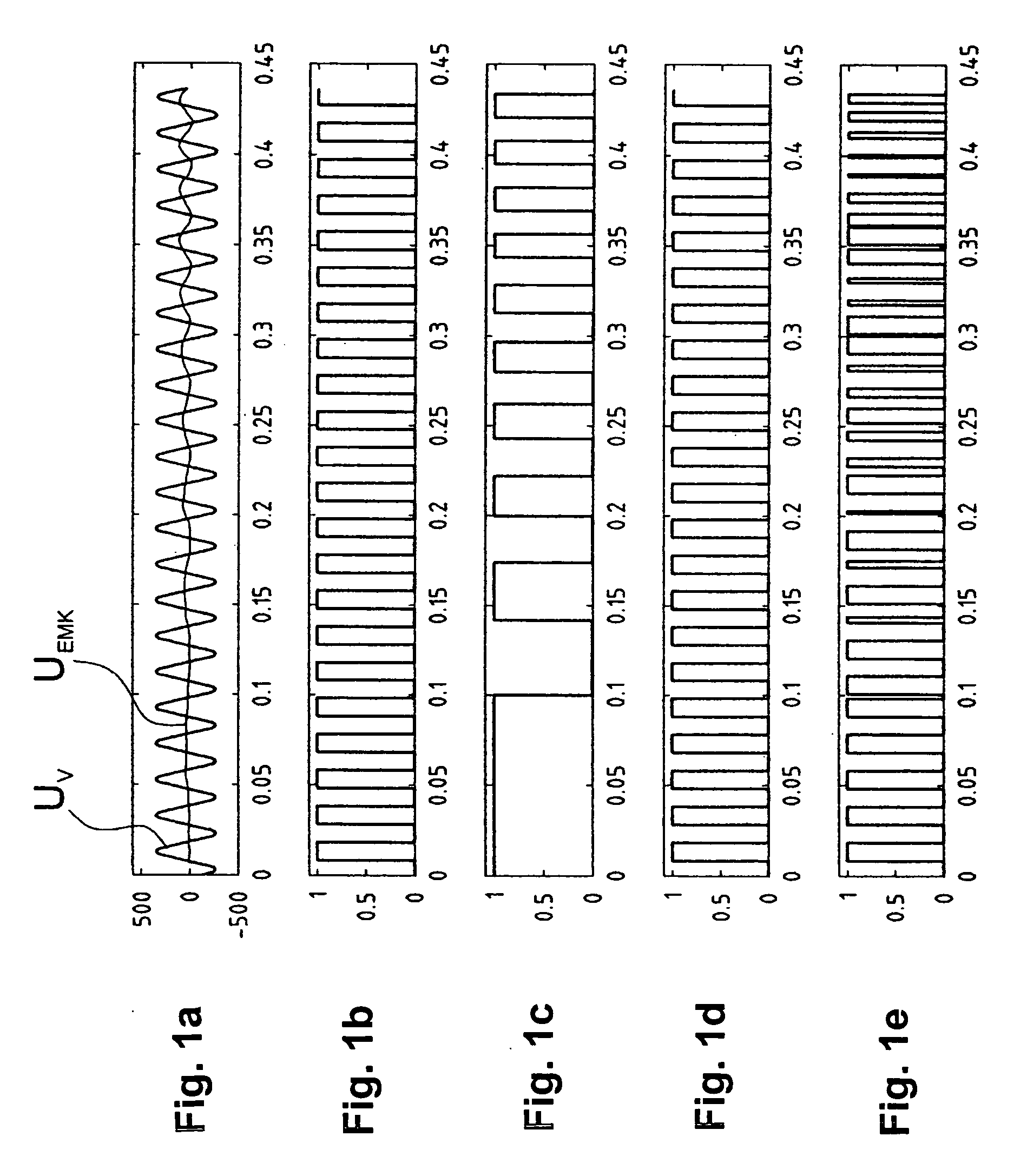
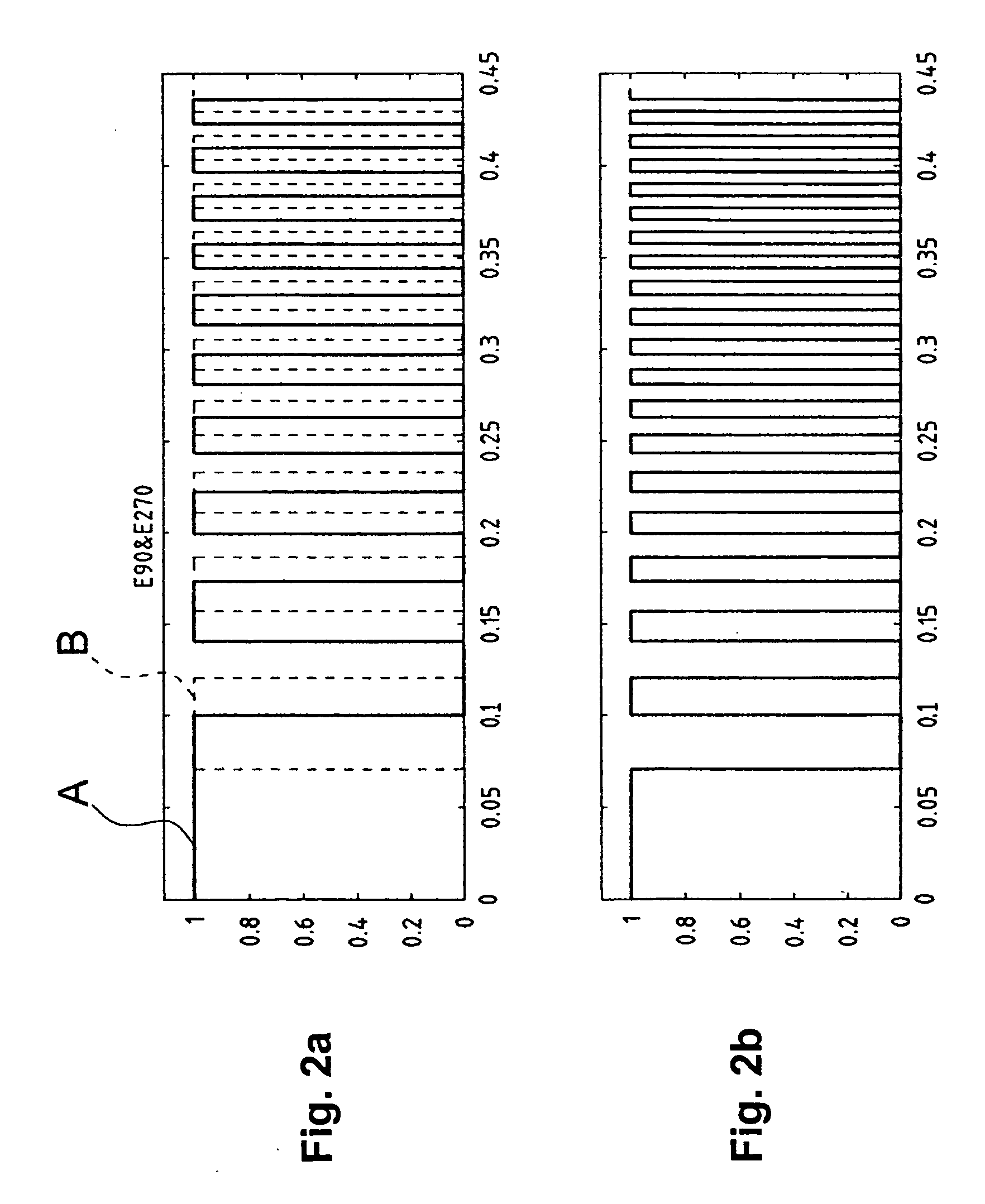
[0036]FIG. 1 in total shows five diagrams a, b, c, d and e, whose time axes run horizontally and correspond to one another. The temporal course of the supply voltage UV as well as the temporal course of the voltage UEMF induced in a winding are plotted in FIG. 1a. Whilst the supply voltage UV represents the common 50 Hz alternating voltage signal, the course of the induced voltage UEMF displays a typical starting behaviour. At the beginning of the rotation of the rotor, the voltage induced in the winding increases only gradually, and with this, the period corresponds to the reciprocal rotor speed. According to the firing rule a, the supply voltage UV is only to be connected to the winding when the voltage UEMF induced in this winding has the same polarity as the supply voltage UV. The polarity of the supply voltage UV over its temporal course is represented in FIG. 1d, wherein the value zero corresponds to a negative polarity and the value 1 to a positive polarity. For the applicati...
PUM
 Abstract
Description
Claims
Application Information
 - R&D
- Intellectual Property
- Life Sciences
- Materials
- Tech Scout
- Unparalleled Data Quality
- Higher Quality Content
- 60% Fewer Hallucinations
Browse by: Latest US Patents, China's latest patents, Technical Efficacy Thesaurus, Application Domain, Technology Topic, Popular Technical Reports.
© 2025 PatSnap. All rights reserved.Legal|Privacy policy|Modern Slavery Act Transparency Statement|Sitemap|About US| Contact US: help@patsnap.com


