Current control method and application thereof

a current control and current control technology, applied in the field of electric circuits, can solve problems such as unnecessary power consumption, and achieve the effect of reducing power consumption in the circui

Active Publication Date: 2006-02-16
SEMICON COMPONENTS IND LLC
View PDF5 Cites 3 Cited by
  • Summary
  • Abstract
  • Description
  • Claims
  • Application Information

AI Technical Summary

Benefits of technology

[0008] The present invention was developed in view of the aforementioned problems. It is therefore an object of the present invention to provide a technique for reducing power consumption in a circuit with an amplifier.
[0009] An aspect of the present invention relates to a control method. The method includes varying the value of a current required for an amplifier to operate, in response to the operational frequency of the amplifier when the current is supplied to the amplifier. The method allows for supplying a current enough for the amplifier to operate at a high operational frequency while switching the supply current to a lower current for the amplifier to operate at a lower operational frequency, thereby reducing power consumption.
[0018] Said operational frequency may be increased by said frequency control means as the number of said series becomes larger, and said current to be provided to said amplifier may be increased by the current control means as said operational frequency becomes higher. Thereby, an enough current to operate the amplifier can be supplied adequately. Said current control means may reduce a current to be supplied to the amplifier as said operational frequency becomes lower. Thereby, power consumption can be reduced. The above mentioned control of the current or the frequency may be the digital or discrete changeover. The current or the frequency can be changed dynamically. The current or the frequency changeover may be correspond to the changeover of the operating mode of the electric device system. The current or the frequency can be arbitrarily changed at operating, for example, corresponding to the low power mode.
[0020] When the receiver is operated in a mode where analog signals are received by one antenna, the frequency control means may specify lower operational frequency than an operational frequency in a diversity reception mode where analog signals are received by a plurality of antennas. Said current control means may increase said current to be supplied to said amplifier as said operational frequency becomes higher.

Problems solved by technology

However, when operated in an operation mode at a lower operational frequency, the circuit designed as described above supplied current more than necessary, causing unnecessary power consumption.

Method used


Image

  • Current control method and application thereof
  • Current control method and application thereof
  • Current control method and application thereof

Examples


first embodiment

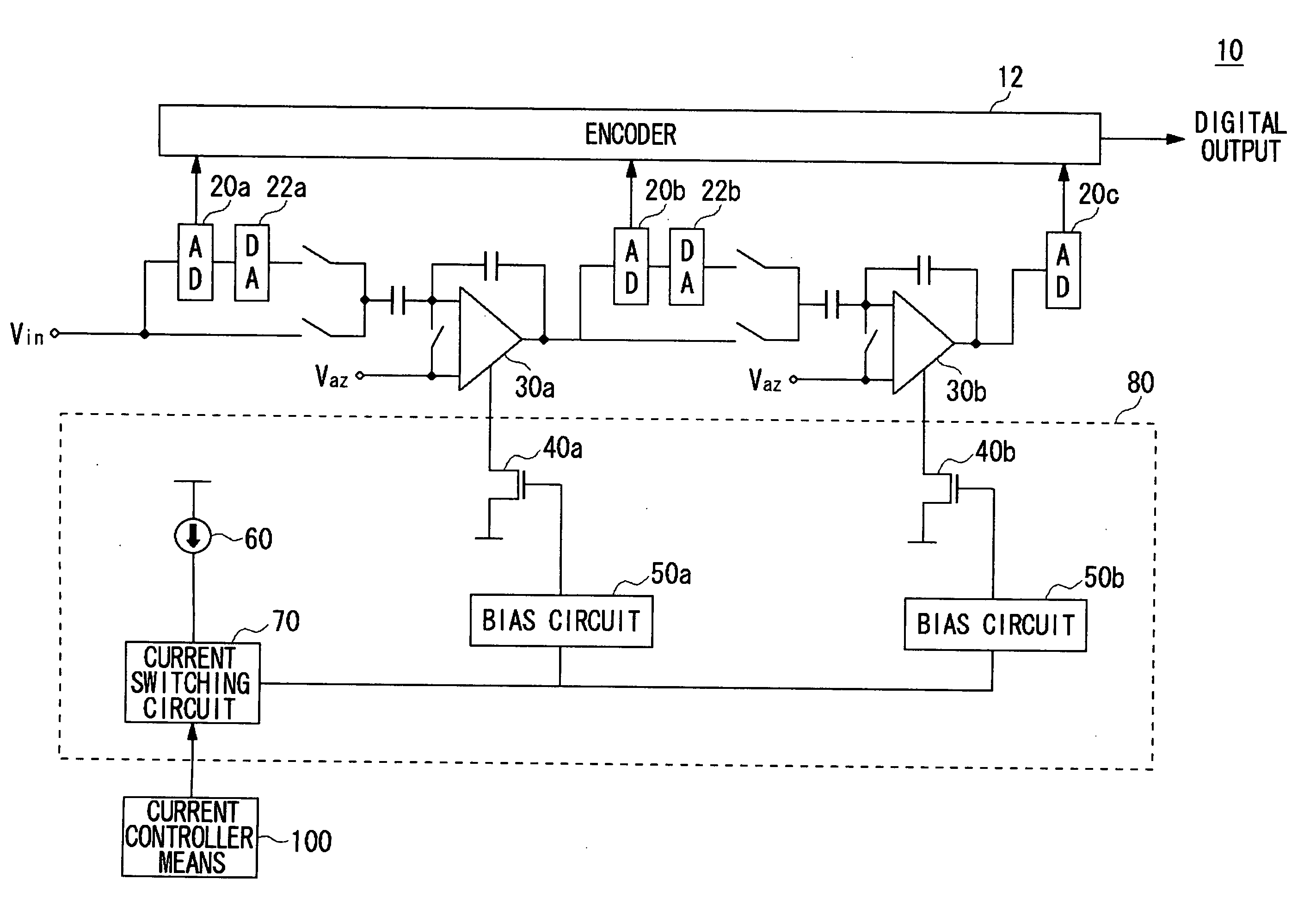
[0029]FIG. 1 illustrates the overall configuration of a pipelined AD converter 10 according to a first embodiment of the present invention. An input analog signal Vin to the input terminal is supplied to a first-stage sub-AD converter 20a to be converted into a digital signal of a predetermined number of bits. This digital signal is delivered to an encoder 12 and a sub-DA converter 22a. The sub-DA converter 22a converts the digital signal delivered from the sub-AD converter 20a to an analog signal. An output signal from the sub-DA converter 22a is then subtracted from the input signal to the sub-AD converter 20a and then amplified at an operational amplifier 30a, thereby providing an input signal to a sub-AD converter 20b in the next stage. The aforementioned signal processing is repeated for a predetermined number of stages to perform AD conversion in a stepwise manner, finally allowing a digital signal to be delivered from the encoder 12.

[0030] The pipelined AD converter 10 inclu...

second embodiment

[0040]FIG. 5 illustrates the overall configuration of a pipelined AD converter 10 according to a second embodiment of the present invention. In the first embodiment, the single current switching circuit 70 switches between the bias currents supplied to all the operational amplifiers 30. However, this embodiment provides current switching circuits 70a and 70b which can switch between bias current values for each of the operational amplifiers 30. The same components as those of the pipelined AD converter 10 according to the first embodiment shown in FIG. 1 are indicated with the same reference symbols. The following descriptions are mainly made to the functions that are different from those of the first embodiment.

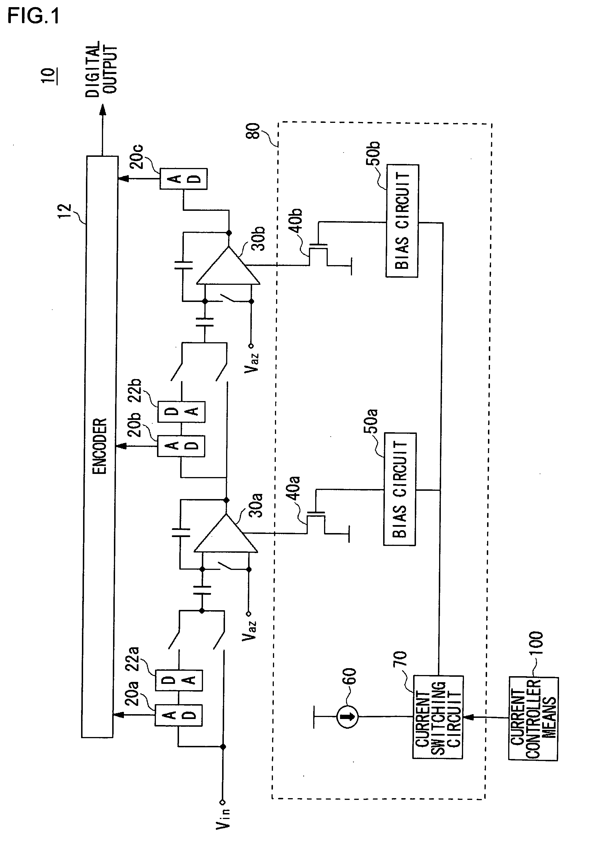
[0041] The current switching circuits 70a and 70b receive a current control signal from the current controller 100 to switch between the values of a current to be delivered to the bias circuits 50a and 50b, respectively. The circuit configuration of the current switching ci...

third embodiment

[0042]FIG. 6 shows the overall configuration of a receiver 200 according to the third embodiment of the present invention. The receiver 200 is a portable type television. The receiver 200 decodes a MPEG stream in a received broadcast wave and reproduces it. The receiver 200 comprises an antenna 102a and an antenna 102b, and it is capable of diversity reception. By receiving broadcast waves by the diversity reception, even when signal received by the antenna 102a is disturbed by multipath interference caused by reflection wave and so forth, the MPEG stream can be adequately reproduced by utilizing signals received by the other antenna 102b.

[0043] The broadcast signals received by antenna 102a are band-limited by a BPF (Band Pass Filter) 104a. Thereafter, the broadcast signals are amplified by a LNA (Low Noise Amplifier) 106a and inputted to a frequency converting IC 110. In the frequency converting IC 110, the broadcast signal is multiplied by an orthogonal oscillation signal by a m...


PUM


Abstract

A current supply circuit supplies a bias current to operational amplifiers which constitute a pipelined AD converter. A current switching circuit switches between output currents in response to a current control signal from current control means, thereby switching between currents to be supplied from a bias circuit to the operational amplifiers via transistors. A sufficiently large current enough for the amplifiers to operate at a high frequency is supplied, while the current is switched to a lower supply current for the amplifier to operate at lower frequencies.

Description

BACKGROUND OF THE INVENTION [0001] 1. Field of the Invention [0002] The present invention relates to electric circuits, and more particularly to a semiconductor circuit, an AD converter, an electronic device, or a receiver with an amplifier, a current supply circuit for supplying a current to the amplifier, and a method for controlling a current to be supplied to the amplifier. [0003] 2. Description of the Related Art [0004] An example of the circuits for converting an input analog signal to a digital signal is a pipelined AD converter. The pipelined AD converter includes low-bit sub-AD converters which are arranged in multiple stages to allow each of the sub-AD converters to perform AD conversion in a stepwise manner. The pipelined AD converter is configured such that an operational amplifier is interposed between the stages of the sub-AD converters to amplify an input analog signal to the sub-AD converter in the next stage. [0005] A single pipelined AD converter may be operated at...

Claims


Application Information

Patent Timeline
Patent Type & Authority Applications(United States)
IPC IPC(8): H03M1/12H03M1/00H03M1/16H03M1/44
CPCH03M1/002H03M1/44H03M1/167
Inventor NAKAMORI, TAKAFUMIWADA, ATSUSHI
Owner SEMICON COMPONENTS IND LLC
Why Eureka
Try Eureka