

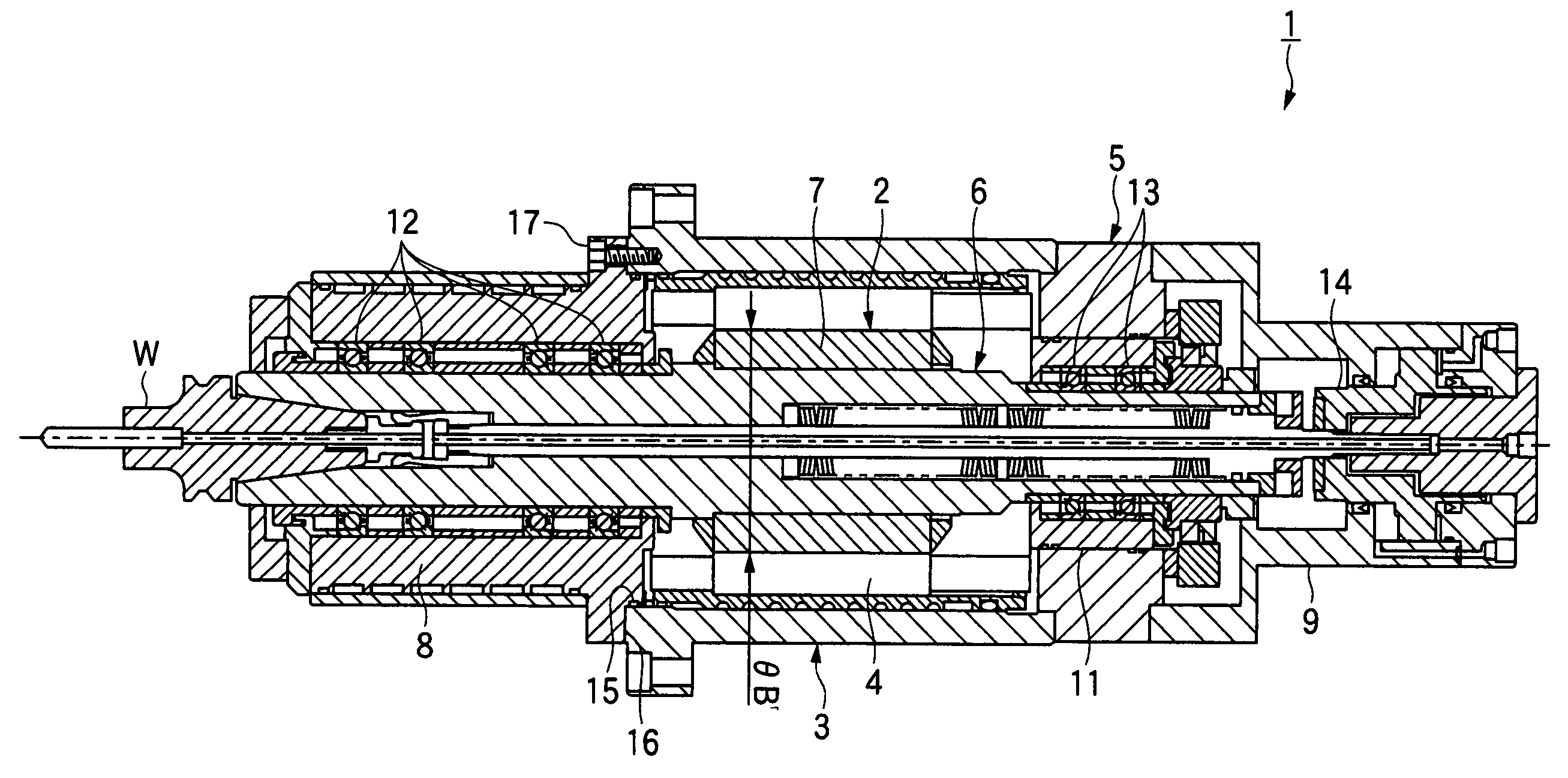
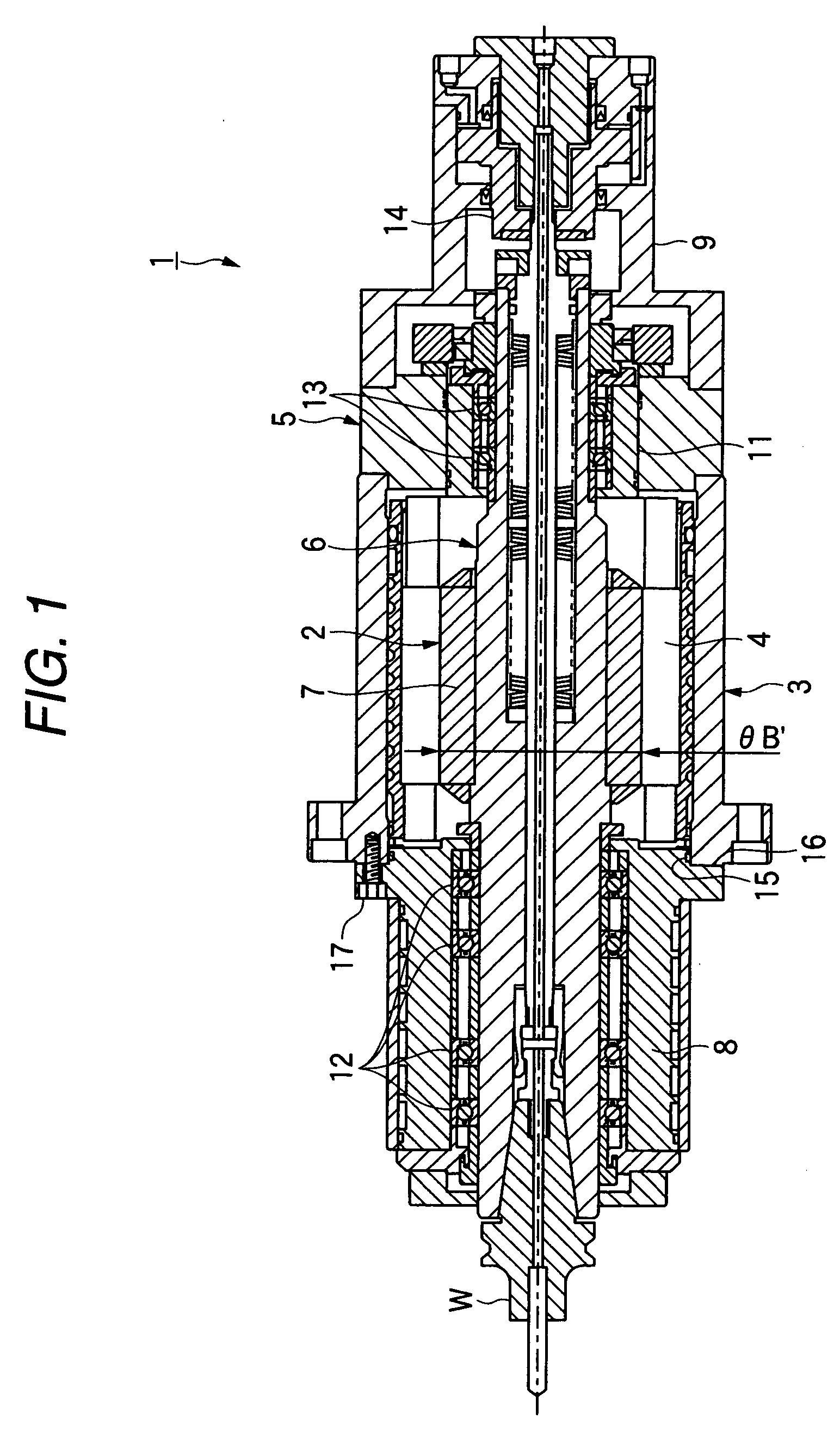
Main shaft device and machine tool with the same
a technology of main shaft and machine tool, which is applied in the direction of attachable milling devices, chucks, manufacturing tools, etc., can solve the problems of frequent failure of spindle, poor operating efficiency, and long downtime, and achieve the effect of convenient disassembly, easy disassembly and easy disassembly
- Summary
- Abstract
- Description
- Claims
- Application Information
AI Technical Summary
Benefits of technology
Problems solved by technology
Method used
Image

Examples
example
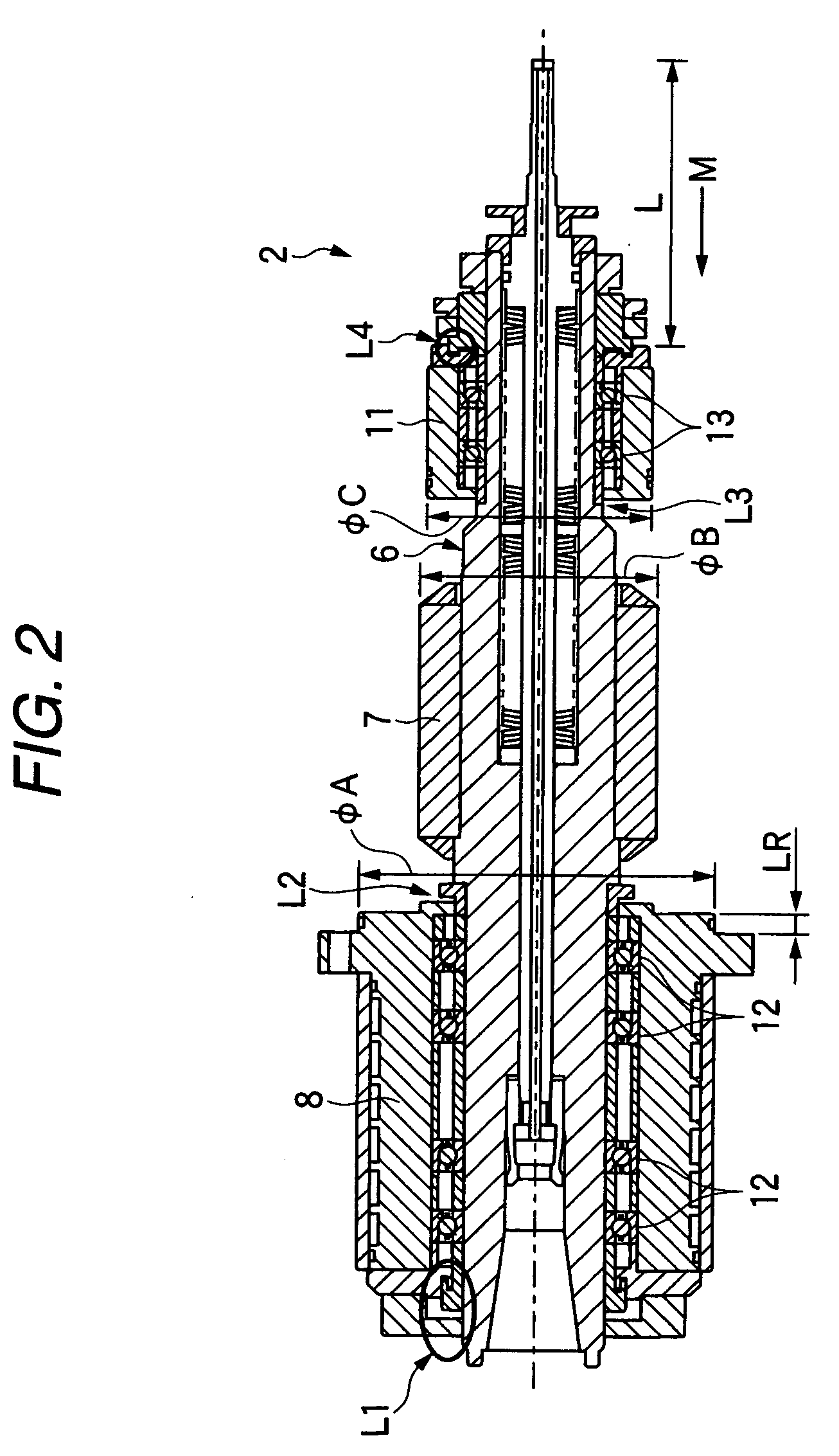
[0169] Next, a description will be given of the results of measurement of stiffness conducted by using a testing device 110 (its essential portions are shown in FIG. 16 by way of example).
[0170] The testing device 110 is disposed such that a dummy sleeve housing 112 with an inside diameter of 85 mm is fitted in a dummy bearing sleeve 111 with an outside diameter of 85 mm by providing a fitting gap of 150 μm, the dimensions being identical to those of the actual spindle apparatus 80. The two O-ring bearings 96 are provided on the front side bearing side (left-hand side in FIG. 16) of the dummy sleeve housing 112, the two O-ring bearings 97 are similarly provided in parallel on the rear side bearing side (right-hand side in FIG. 16) of the dummy bearing sleeve 111. The O-ring 94 with an inside diameter of 84.5 mm and a size of 2 mm is installed in each of the O-ring bearings 97 and 96. In addition, a pickup of an electric micrometer is attached to an outer peripheral surface 113 of t...
PUM
| Property | Measurement | Unit |
|---|---|---|
| Fraction | aaaaa | aaaaa |
| Diameter | aaaaa | aaaaa |
| Length | aaaaa | aaaaa |
Abstract
Description
Claims
Application Information