Weighted surface-to-surface mapping

Active Publication Date: 2006-02-16
ELEKTA AB
View PDF65 Cites 36 Cited by
  • Summary
  • Abstract
  • Description
  • Claims
  • Application Information

AI Technical Summary

Benefits of technology

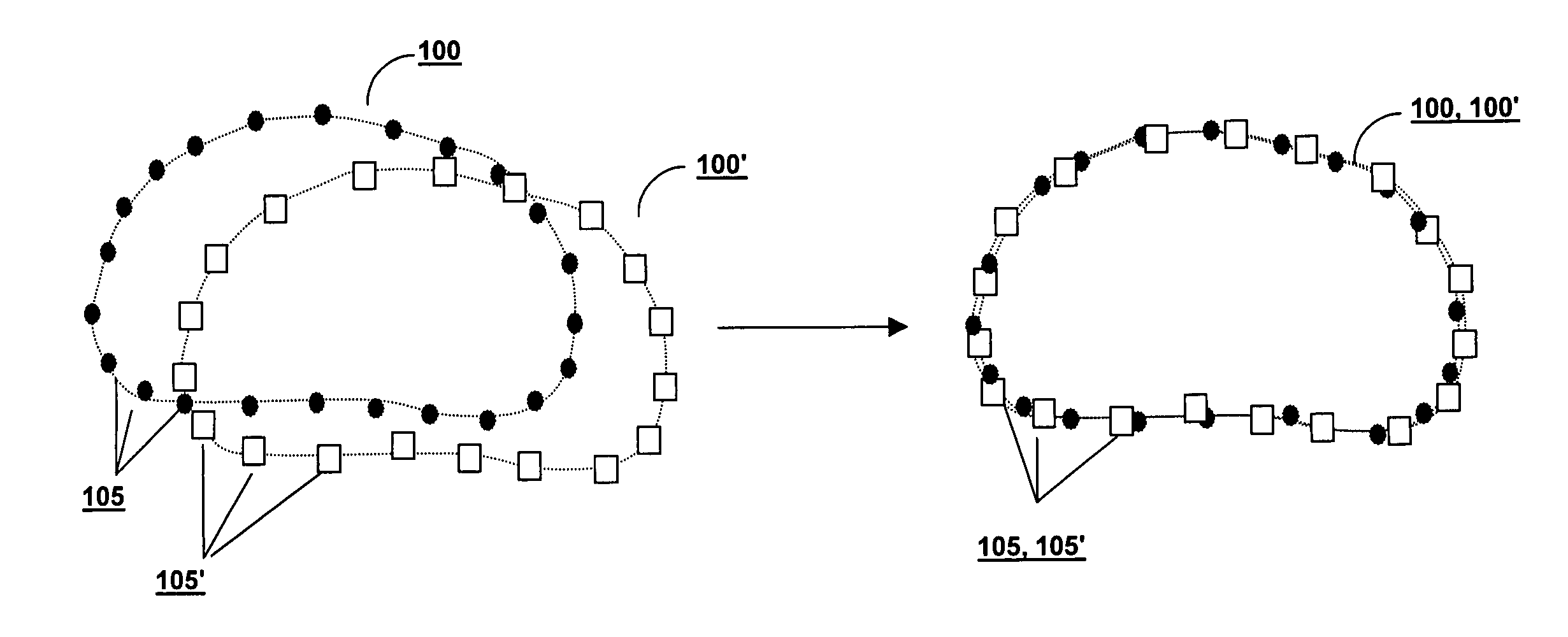
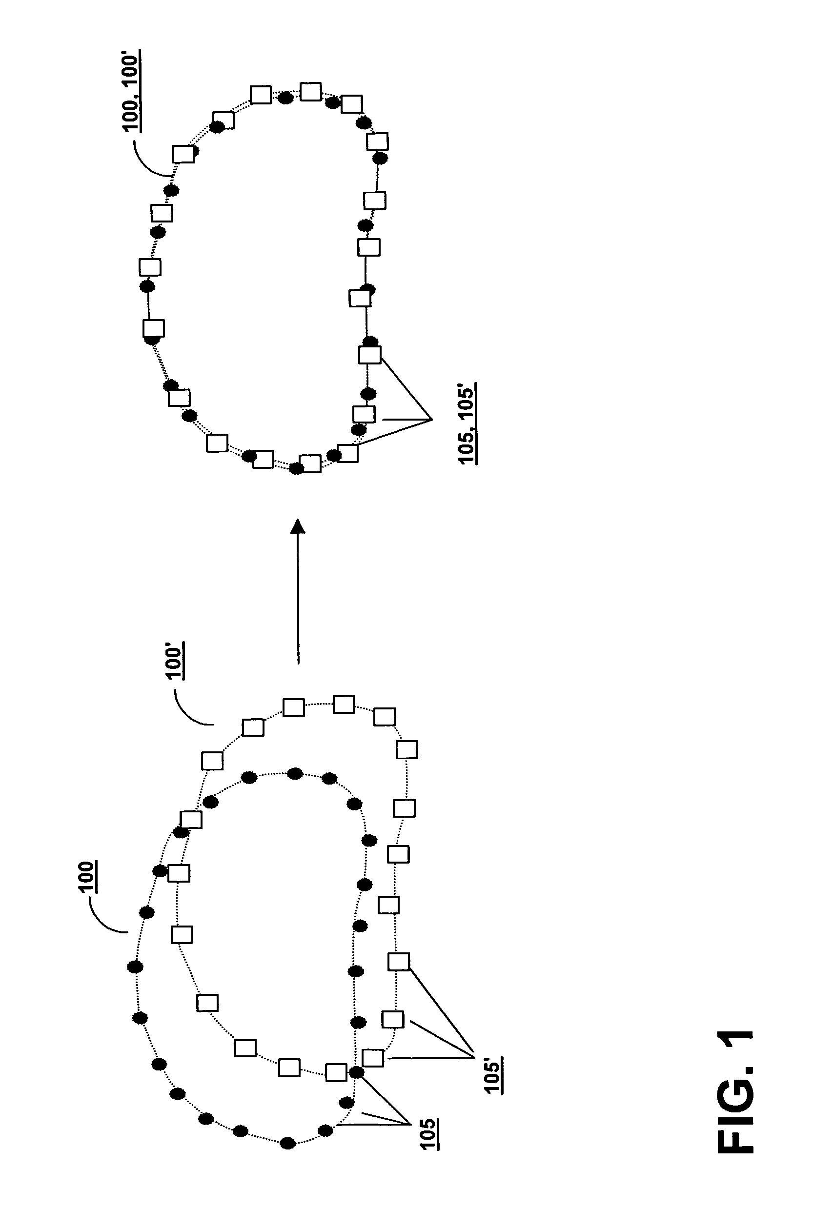
[0006] The present invention provides systems and methods for determining patient positioning corrections to compensate for organ displacement and morphological change based on surface models derived from medical images taken at different times. In general, the invention relates to weighting one or more surface elements identified in at least two medical images t

Problems solved by technology

Because organs can change location and/or shape from fraction to

Method used


Image

  • Weighted surface-to-surface mapping
  • Weighted surface-to-surface mapping
  • Weighted surface-to-surface mapping

Examples


Embodiment Construction

[0022] Imaging is often used by oncologists in determining the treatment parameters of radiation therapy plans such that the prescribed radiation is sufficient to eliminate the cancerous cells and while conforming the shape of the dose distribution to a target volume to the greatest extent possible, thereby sparing healthy tissue from exposure to potentially harmful doses of radiation. To develop a preferred treatment plan, simulations can be performed to design a set of beams which accomplish this goal that calculate the dose at each point in the patient resulting from this set of beams. The dose distribution can be represented, for example, as isodose lines or as 3D isodose surfaces within the patient. The treatment goal is to encompass the lesion and an appropriate safety margin within the 100% isodose surface. The treatment plan is then administered, usually at a later date and over a period of weeks, based on the treatment parameters. One shortcoming of this approach is that th...


PUM


Abstract

A displacement of a lesion within a patient is determined for the purpose of administering radiation treatment by generating sets of surface elements from three-dimensional images of the lesion taken at different times. Weights are assigned to the surface elements, and based on weights and the proximity of corresponding elements in one set to elements in another set, a displacement is determined.

Description

TECHNICAL FIELD [0001] This invention relates to methods and systems for verifying anatomical features of a patient undergoing radiation therapy and, more particularly, to methods and systems for identifying common surface elements of anatomical elements common to multiple images. BACKGROUND INFORMATION [0002] Radiation-emitting devices are used for the treatment of cancerous tumors within patients. The primary goal of treating cancerous tumors with radiation therapy is the complete eradication of the cancerous cells, while the secondary goal is to avoid, to the maximum possible extent, damaging healthy tissue and organs in the vicinity of the tumor. Typically, a radiation therapy device includes a gantry that can be rotated around a horizontal axis of rotation during the delivery of a therapeutic treatment. A particle linear accelerator (“LINAC”) is located within the gantry, and generates a high-energy radiation beam of therapy, such as an electron beam or photon (x-ray) beam. The...

Claims


Application Information

Patent Timeline
IPC IPC(8): A61B5/05
CPCA61B6/04A61N5/1049G06T2207/30004G06T7/0038G06T7/0044A61N2005/1061G06T7/38G06T7/74G06T19/20G06T2219/2004G06T2219/2016
Inventor LACHAINE, MARTINFALCO, TONY
Owner ELEKTA AB
Why Eureka
Try Eureka