Ignition system with driver identification

a technology of ignition system and driver identification, which is applied in the direction of process and machine control, program control, anti-theft devices, etc., can solve the problems of impaired operators with slower reaction time, difficult for an unauthorized user to start, and no simple system to positively/biometrically, etc., to achieve the effect of slow reaction tim

Inactive Publication Date: 2006-02-16
ELAINE E FUTRELL
View PDF4 Cites 105 Cited by
  • Summary
  • Abstract
  • Description
  • Claims
  • Application Information

AI Technical Summary

Benefits of technology

[0016] One advantage of the present invention is the inhibition of operation of a motor vehicle by an unauthorized user. The system acts as a theft deterrent because it would be difficult for an unauthorized user to start the vehicle due to lack of biometric identifying factors, and without knowing the proper functions and the proper sequence.
[0017] Another advantage of the present invention is the inhibition of operation of a motor vehicle by potential operators whose motor skills are diminished due to excessive alcohol consumption, or drug use, or sleep deprivation, or any other factor that would render them impaired such as the onset of dementia. If the timing function “maxes out” before the proper sequence is performed, the vehicle ignition system is prevented from engaging. Thus, although a sober operator can readily

Problems solved by technology

None of these references provide a simple system to positively/biometrically identify a potential operator and/or deter unauthorized/impaired use of a motor vehicle that utilizes input from the vehicle's functional devices.
The system acts as a theft deterrent because it would be difficult for an unauthorized u

Method used


Image

  • Ignition system with driver identification
  • Ignition system with driver identification
  • Ignition system with driver identification

Examples


Embodiment Construction

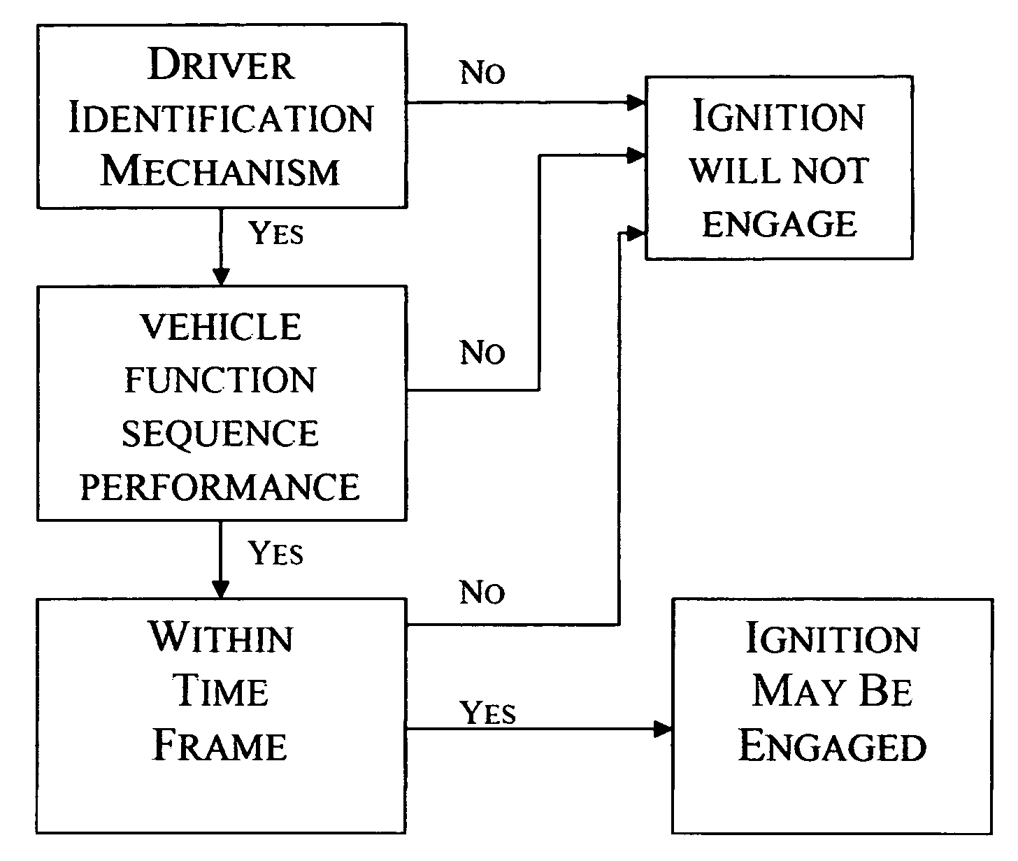
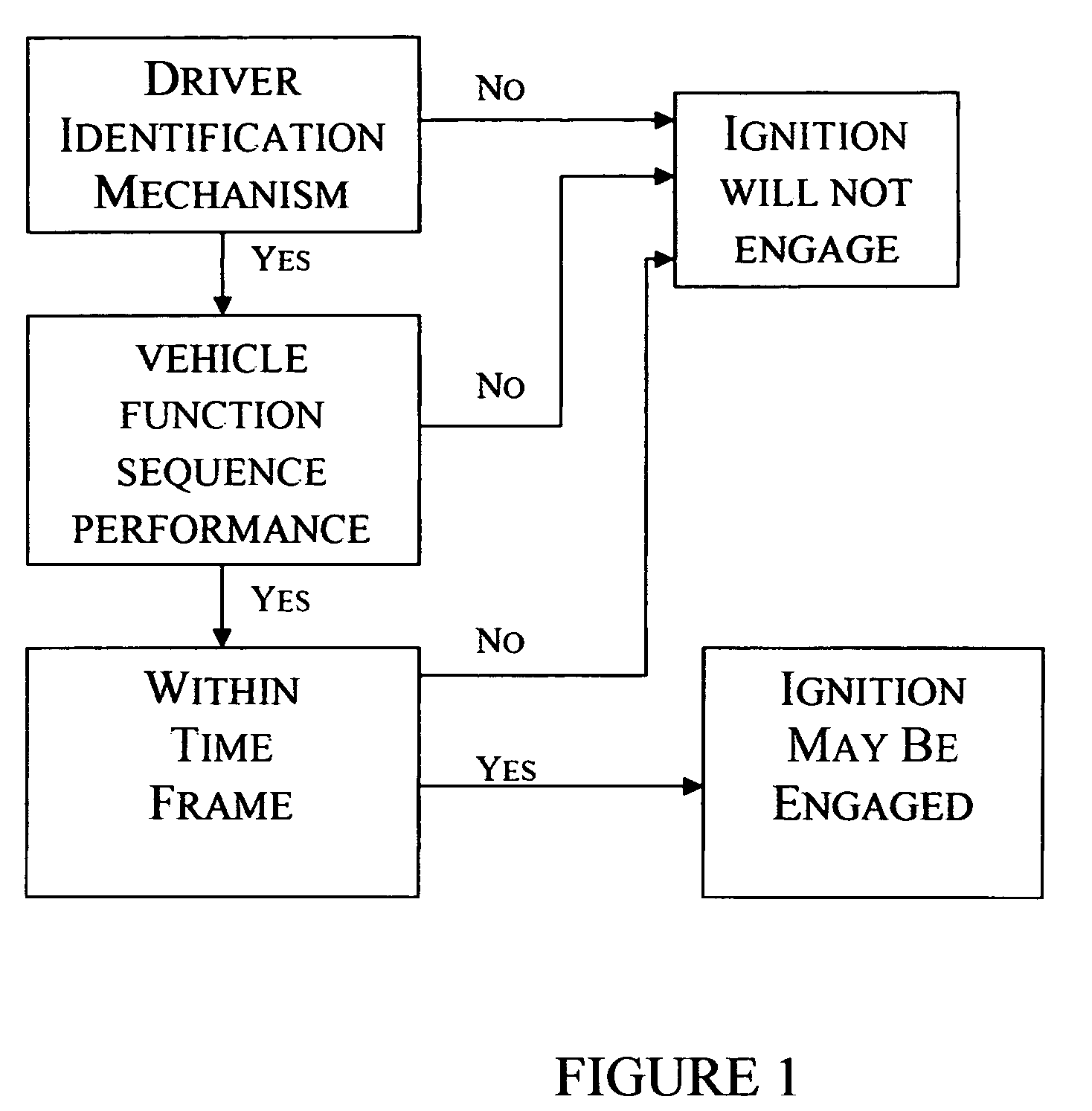
Operation of the Invention

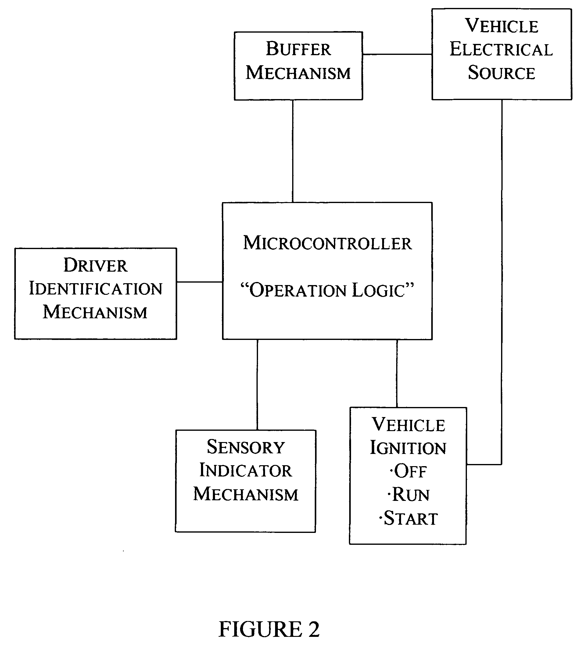
[0054] With reference to the accompanying drawings, FIG. 3 a schematic representation of system 10 is provided. In a preferred embodiment, the system 10 includes a buffer filter or buffer mechanism 14 generally operable to convert an initial vehicle voltage, i.e. 12 volts, into a voltage useable by the system 10, i.e. 3.3 volts. A reset mechanism 18 operates to reset or initialize the system mechanisms. The preferred system 10 further includes a delay mechanism 22. In the preferred embodiment, delay mechanism 22 generally operates as an anti-noise interrupt mechanism. Delay mechanism 22 delays the electrical signal from the vehicle electrical source, or battery, when the vehicle ignition is placed in a run / start position.

[0055] System 10 includes a microcontroller 34 which performs the sequencing function generally operable to receive inputs from a plurality of pre-selected vehicle function devices as will be explained in further detail below. In a prefe...


PUM


Abstract

System and method for positively identifying an operator through biometric means which shall prevent unauthorized or impaired operation of a motor vehicle by requiring the potential operator to sequentially energize several vehicle devices, within a set time period, prior to placing the vehicle ignition into a start position. The system includes a device for measuring an operator's biometric identification, and a microcontroller. Logic outputs from the sequencing mechanism and the timer mechanism are contained within the microcontroller operating as a logic decoder that is used to control the vehicle ignition circuit. The microcontroller monitors the sequence in which the vehicle's devices are energized, and if they are energized within the correct order and within the predetermined amount of time then the microcontroller will output a signal to allow the ignition circuit to close. A sensory indicator may alert the potential operator as to the condition of the microcontroller output. An unauthorized user is inhibited from operating the motor vehicle because their identification could not be biometrically established and/or the performance sequence is unknown to him/her. Slower reflex times or impaired motor skills may also prevent an impaired operator from performing the proper sequence within the predetermined time period.

Description

[0001] This application claims the benefit of a Provisional Patent Application No. 60 / 591412 filed Jul. 27, 2004 entitled: IGNITION SYSTEM WITH DRIVER IDENTIFICATION. This application also claims the benefit of Non-Provisional Patent U.S. Pat. No. 6,920,389 issued Jul. 19, 2005 entitled IGNITION SYSTEM issued to all of the same inventors as is listed in this application.BACKGROUND OF THE INVENTION [0002] 1. Field of the Invention [0003] The present invention relates to systems for biometrically identifying a potential operator through thumbprint, fingerprint, iris, voice recognition or other biometric means of identifying an individual for the purpose of inhibiting potential impaired operators and unauthorized persons from operating a motor vehicle. Additionally, the present invention relates to other systems, devices, and methods for inhibiting potential impaired operators and unauthorized persons from operating a motor vehicle. Furthermore, the invention provides systems, devices,...

Claims


Application Information

Patent Timeline
IPC IPC(8): B60R22/00
CPCB60R25/2009B60R25/25B60R25/257B60R25/255B60R25/252
Inventor HALE, HOWARD STANLEYFUTRELL, ELAINE ELIZABETH
Owner ELAINE E FUTRELL
Why Eureka
Try Eureka