Fuel vaporizing device

a fuel vaporizing and fuel technology, applied in the direction of machines/engines, electrochemical generators, combustion types, etc., can solve the problem that the steam reforming reaction is barely progressing, and achieve the effect of improving the reforming efficiency and starting performance of the fuel reforming devi

Active Publication Date: 2006-02-23
NISSAN MOTOR CO LTD
View PDF9 Cites 32 Cited by
  • Summary
  • Abstract
  • Description
  • Claims
  • Application Information

AI Technical Summary

Benefits of technology

[0009] It is therefore an object of this invention to improve the ref

Problems solved by technology

When this temperature is reached, the partial oxidation reaction is already in ful

Method used


Image

  • Fuel vaporizing device
  • Fuel vaporizing device
  • Fuel vaporizing device

Examples


Embodiment Construction

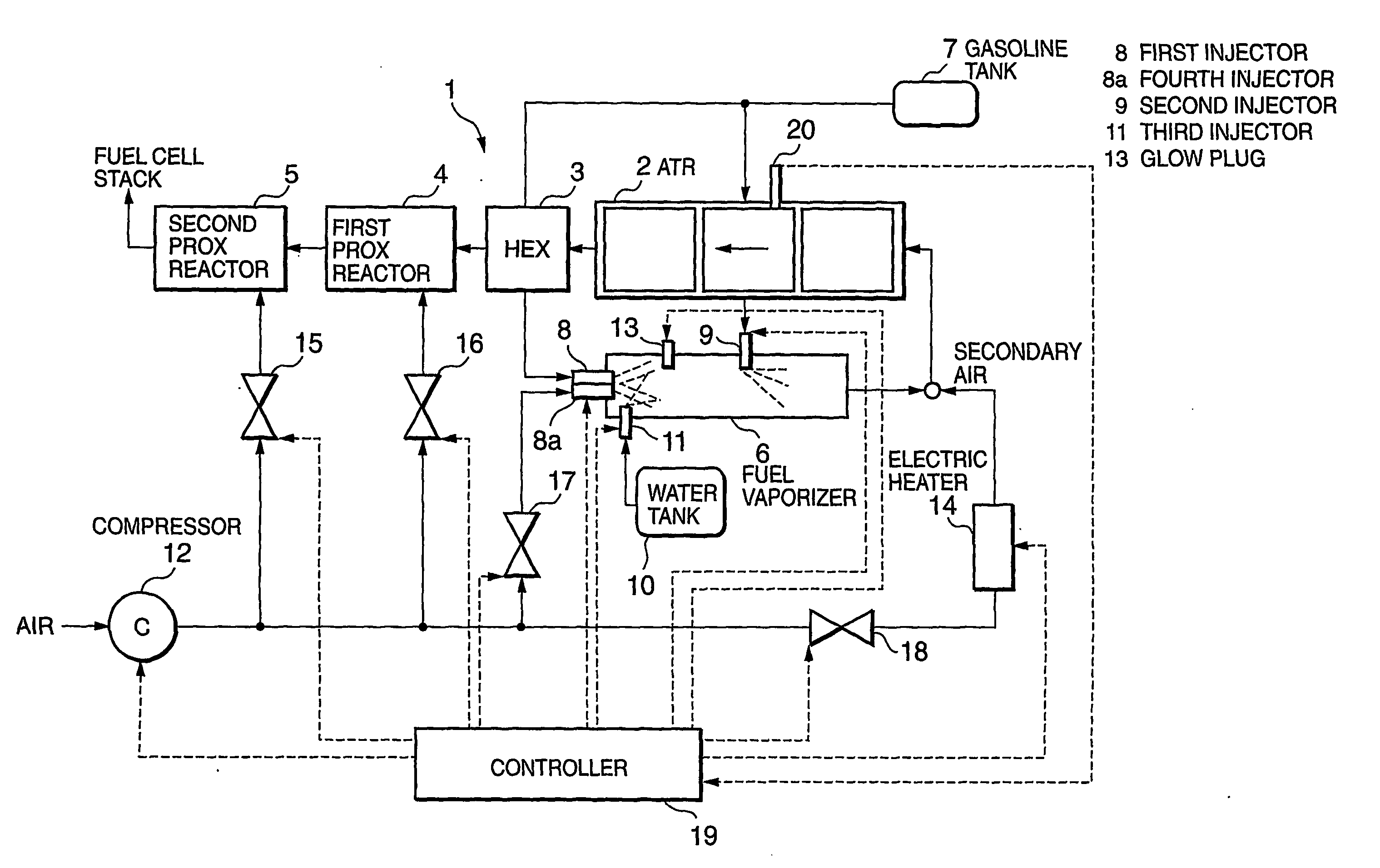
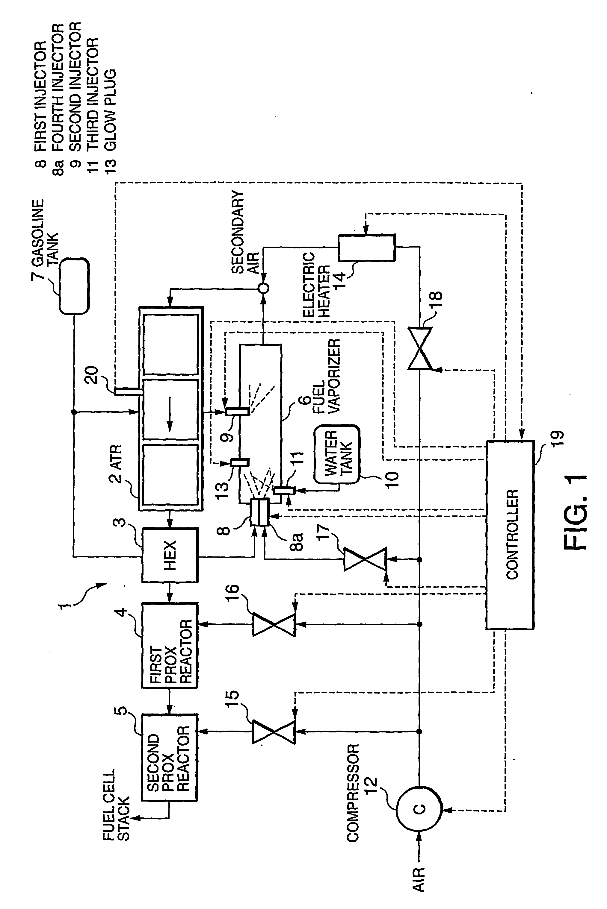
[0017] Referring to FIG. 1 of the drawings, a fuel reforming device 1 for use in a fuel cell system comprises an autothermal reformer (ATR) 2 filled with a steam reforming catalyst, a heat exchanger (HEX) 3 which heats fuel by means of heat exchange between fuel and reformate gas, a first carbon monoxide preferential oxidation reactor (PROX reactor) 4 which removes carbon monoxide from the reformate gas, a second carbon monoxide preferential oxidation reactor (PROX reactor) 5, and a cylindrical fuel vaporizer 6 which supplies fuel vapor to the reformer 2.

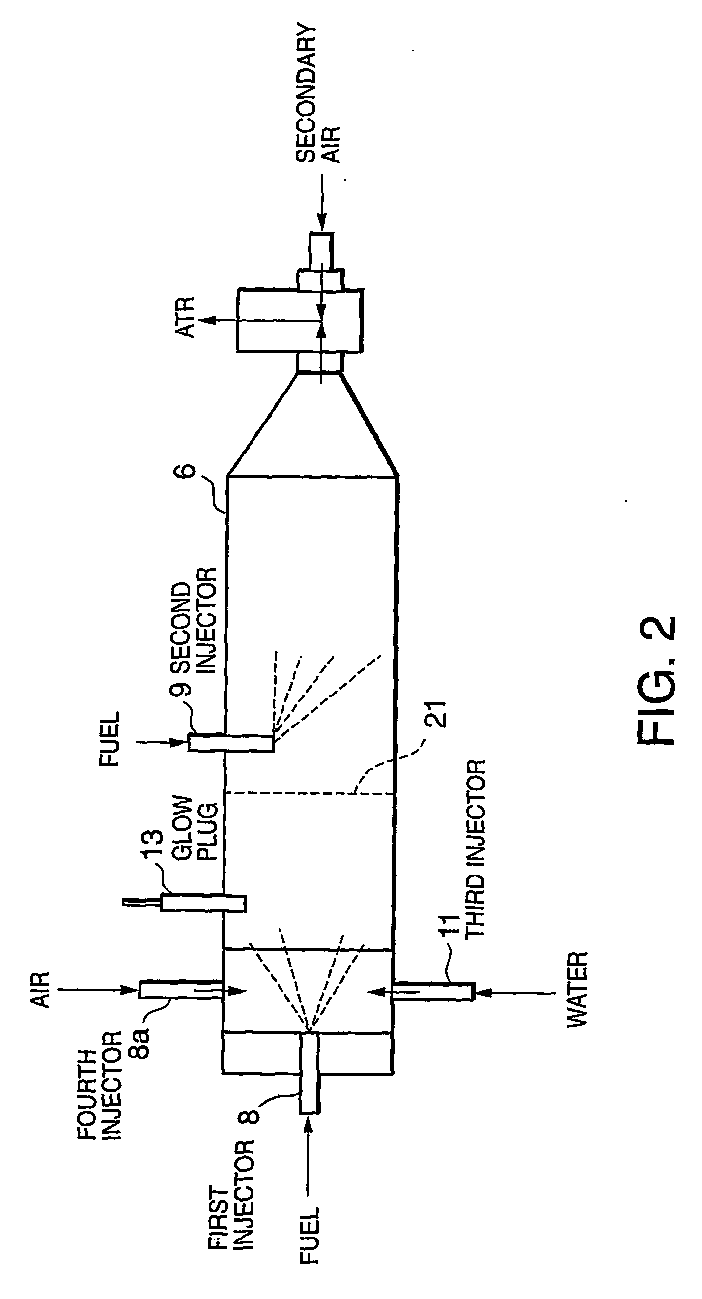
[0018] The fuel reforming device 1 further comprises a gasoline tank 7 which stores the gasoline as fuel, a first injector 8 disposed in an upstream portion of the fuel vaporizer 6, and a second injector 9 disposed in a downstream portion of the fuel vaporizer 6. The fuel reforming device 1 injects gasoline into the fuel vaporizer 6 through the first injector 8 and second injector 9. The fuel reforming device 1 further comprises a ...


PUM

PropertyMeasurementUnit
Temperatureaaaaaaaaaa
Ratioaaaaaaaaaa

Abstract

Hydrogen-rich reformate gas is produced by a fuel reformer (2) from fuel vapor containing hydrocarbon, which is produced by a fuel vaporizer (6), by means of a partial oxidation reaction and a steam reforming reaction. A fuel injector (8, 9) supplies fuel to the fuel vaporizer (6), and an air injector (8a) supplies air to the fuel vaporizer (6). A glow plug (13) partially oxidizes the air-fuel mixture inside the fuel vaporizer (6). By controlling the air supply amount in relation to the fuel supply amount to obtain an excess air factor corresponding to a predetermined rich air-fuel ratio, a part of the air-fuel mixture in the fuel vaporizer (6) is partially oxidized, and the remaining fuel vapor is heated by the oxidation heat. As a result, the partial oxidation reaction and steam reforming reaction in the fuel reformer (2) are performed with a favorable balance.

Description

FIELD OF THE INVENTION [0001] This invention relates to the supply of fuel vapor to a fuel reformer which reforms hydrocarbon fuel to extract hydrogen. BACKGROUND OF THE INVENTION [0002] JP2001-223016A, JP2001-210347A, JP2001-27403A, JP2000-63104A, Tokkai Hei 8-189380, Tokkai Hei 8-188784, Tokkai Hei 8-2901, Tokkai Hei 7-172802, and Tokkai Hei 7-103090, published by the Japan Patent Office, are known in relation to a fuel reforming device which extracts hydrogen from hydrocarbon fuel such as gasoline or methanol in order to operate a fuel cell system. SUMMARY OF THE INVENTION [0003] To perform a reforming reaction in a reformer, hydrocarbon fuel such as gasoline or methanol and water must be vaporized prior to being supplied to a reforming catalyst. Reforming is performed in the reformer by two types of processes, partial oxidation reforming and steam reforming, as shown in equations (1) and (2). Partial  oxidation  reforming:⁢⁢C8⁢H18+82⁢O2->8⁢CO+9⁢H2+Δ⁢ ⁢Q(1) Steam reforming: C...

Claims


Application Information

Patent Timeline
IPC IPC(8): F01N3/00F23D11/44B01B1/00B01J19/00C01B3/38F23K5/22H01M8/06
CPCB01B1/005C01B2203/82B01J2208/00716B01J2219/00063B01J2219/00132C01B3/382C01B2203/0244C01B2203/044C01B2203/047C01B2203/066C01B2203/0844C01B2203/1288C01B2203/142C01B2203/1604C01B2203/1619B01J19/0013
Inventor KAMIJO, MOTOHISAAOYAMA, TAKASHIIZUMI, TAKAO
Owner NISSAN MOTOR CO LTD
Why Eureka
Try Eureka