Circulation-type liquid cooling apparatus and electronic device containing same

a liquid cooling and electronic device technology, applied in the direction of lighting and heating apparatus, instruments, semiconductor/solid-state device details, etc., can solve the problems of reducing the cooling performance of the system, device-cooling methods based on liquid cooling technology are under investigation, and increasing the amount of heat generated by parts in such electronic devices

Inactive Publication Date: 2006-02-23
NEC DISPLAY SOLUTIONS LTD
View PDF6 Cites 71 Cited by
  • Summary
  • Abstract
  • Description
  • Claims
  • Application Information

AI Technical Summary

Benefits of technology

[0020] It is an object of the present invention to provide a cooling apparatus for an electronic device utilizing a liquid cooling system, which supports any orientation in which the electronic device is installed in whichever direction, and prevents accumulated air from again flowing into a conduit in the event of a change in orientation of the electronic device.
[0022] In the foregoing configuration, the coolant liquid circulating conduit is formed within the tank such that the conduit passes the middle position of the tank, and the coolant liquid circulating conduit is opened at the middle position of the tank. Accordingly, an air layer provided in the tank for alleviating the pressure will not be introduced into the opening of the coolant liquid circulating conduit formed by dividing the conduit by the narrow gap at the middle position of the tank, even if the air layer changes its position in conformity to a change in the orientation of the apparatus. Further, when the orientation of the tank is changed, minute bubbles produced within the conduit can be efficiently removed via the narrow gap formed by dividing the conduit forming area at the middle position of the tank. Consequently, a stable coolant circulation can be ensured in any orientation taken by the apparatus.
[0024] The cooling apparatus according to the present invention, when used, eliminates restrictions on the orientation in which a liquid cooling system is installed, so that liquid cooling technology can be applied as well to electronic devices which can be installed in various orientations, like a projector apparatus.

Problems solved by technology

In recent years, as the performance of electronic devices increases, parts mounted in such electronic devices have generated increasingly more amounts of heat.
Recently, however, device-cooling methods based on liquid cooling technology have been under investigation because of their higher heat radiation performance and quiet operation.
For this reason, anti-freeze condenses over a long-term use, and variations in viscosity due to a change in concentration degrades the coolant circulating performance, resulting in lower cooling performance of the system.
If the bubbles stay within the path and block it, the coolant liquid cannot be circulated, possibly causing a loss in the cooling capabilities of the system.
Also, if the bubbles within the liquid enter a thin flow between a rotor and a main shaft of a circulating pump, a gap is blocked which results in a semi-dry lubrication or a solid lubrication state between the main shaft and the rotor, which causes the generation of sudden abrasive heating which would damage the pump's bearings.
Further, if the bubbles are deposited such that they cause the entire rotor to be surrounded by an air layer, the pump becomes incapable of pumping the coolant liquid, resulting in a failure to circulate the coolant liquid.
When such a liquid cooling system is employed as a cooling means for an electronic device that can be installed in different orientations, depending on the requirements of a particular user, the function of the aforementioned reservoir tank does not work well in some situations.
However, the conventional liquid cooling system is designed on the assumption that the apparatus with which it is used operates in the same orientation at all times. Also, the reservoir tank is not designed to support any orientation in an apparatus in which the reservoir tank is installed at any angle over 360 degrees, rather, the reservoir tank is simply a closed case having an inlet port and an outlet port with a proper amount of coolant liquid 24a stored therein.
The conventional reservoir tank in such a structure is highly likely to significantly lose cooling performance due to an air layer within the tank which readily blocks the conduit inlet and outlet ports, following a change in the position of the apparatus, which prevents the coolant liquid from circulating.
In this structure, the reservoir tank does function without an air within the tank approaching to the opening at the end of the inlet tube within the tank as long as the position is changed within a particular range (from 0° to 90°), but the reservoir tank is not designed to accommodate any changes in positioning from 0° to 360°.
In this arrangement, since the open ends of the inlet tube and outlet tube are exposed, a change in the orientation of the tank is likely to cause air in the reservoir tank to flow again into a conduit.
In other words, even if bubbles in the path are trapped and kept in the air layer within the tank, the bubbles will flow back into the conduit when the orientation of the tank is changed, resulting in a high susceptibility to detrimental effects such as clogging of the conduit by bubbles, damage to a pump, and the like.

Method used


Image

  • Circulation-type liquid cooling apparatus and electronic device containing same
  • Circulation-type liquid cooling apparatus and electronic device containing same
  • Circulation-type liquid cooling apparatus and electronic device containing same

Examples


first embodiment

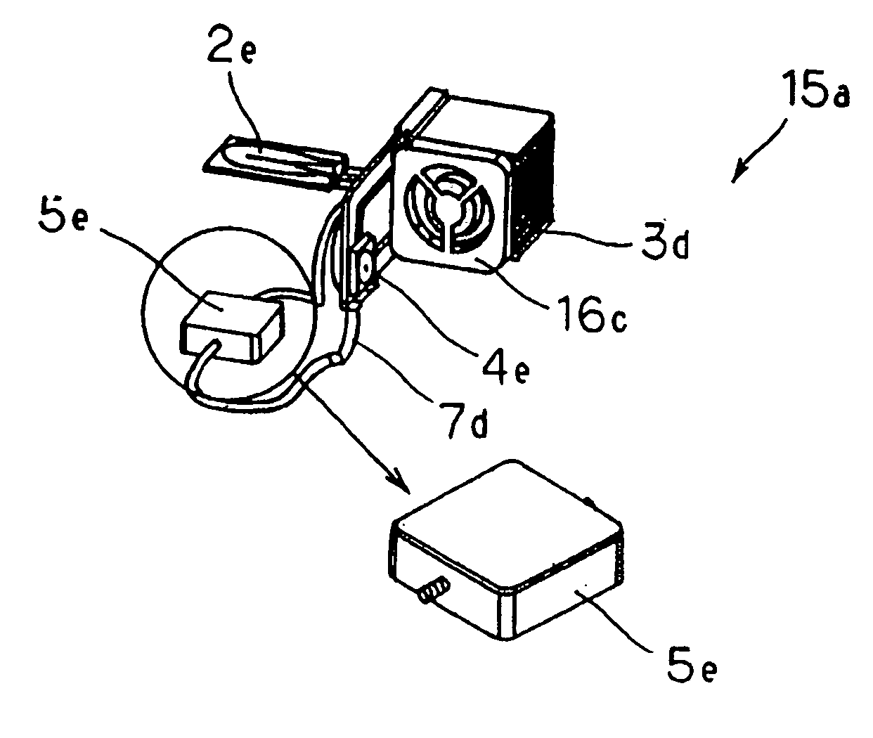
[0064] FIGS. 6 to 10 illustrate the structure of a reservoir tank associated with a cooling apparatus according to a first embodiment of the present invention. FIG. 6 generally illustrates the reservoir tank; FIG. 7 illustrates the internal structure of the reservoir tank; FIG. 8 is a front view of the reservoir tank; FIG. 9 is a vertically sectioned perspective view of the reservoir tank; and FIG. 10 illustrates the structure of the reservoir tank when it is filled with a coolant liquid.

[0065] In FIGS. 6 to 10, cooling apparatus 15a of this embodiment comprises radiator 3d, radiation fan 16c, circulating pump 4e, reservoir tank 5e, and heat receiving element 2e such as a cold plate. Reservoir tank 5e is joined to resin tube 7d, which interconnects components of cooling apparatus 15a, for keeping a coolant liquid, retaining an air layer for buffering thermal expansion of the cooling liquid, and trapping bubbles produced in a circulating system, as illustrated in FIG. 6.

[0066] As i...

second embodiment

[0075] FIGS. 14 to 18 illustrate the structure of a reservoir tank that is contained within a cooling apparatus according to a second embodiment of the present invention. FIG. 14 generally illustrates the reservoir tank; FIG. 15 illustrates the internal structure of the reservoir tank; FIG. 16 is a vertically sectioned, exploded perspective view of the reservoir tank; FIG. 17 is a vertically sectioned perspective view generally illustrating the reservoir tank; and FIG. 18 is a diagram for describing the operation of the reservoir tank.

[0076] Reservoir tank 5f of the second embodiment illustrated in FIGS. 14 to 18 further facilitates the movement of the accumulated air through the gap defined by the cut groove formed in the bridge within the reservoir tank disclosed in the first embodiment, and is characterized by a pair of axially symmetric members which are joined to form the reservoir tank.

[0077] Specifically, as illustrated in FIGS. 15 to 17, reservoir tank 5f comprises a pair,...

third embodiment

[0078] FIGS. 19 to 23 illustrate the configuration of a reservoir tank that is contained within a cooling apparatus according to a third embodiment of the present invention. FIG. 19 generally illustrates the reservoir tank; FIG. 20 illustrates the internal structure of the reservoir tank; FIG. 21 is a horizontally sectioned top plan view of the reservoir tank; FIG. 22 is a vertically sectioned, exploded perspective view of the reservoir tank; and FIG. 23 is a vertically sectioned perspective view generally illustrating the reservoir tank.

[0079] Cooling apparatus 15c of the third embodiment illustrated in FIGS. 19 to 23 makes the circulating system compact by positioning the coolant liquid inlet port and the coolant liquid outlet port of the reservoir tank in the first embodiment on the same side, with the intention of facilitating the mounting of cooling apparatus 15c to an electronic device.

[0080] Specifically, in FIGS. 19 to 23, cooling apparatus 15c of this embodiment comprises...


PUM


Abstract

A cooling apparatus comprises a tank for keeping a coolant liquid therein and having an air layer, a heat receiving element in contact with a heat generating part to receive heat therefrom, a radiator for radiating heat absorbed by a coolant liquid, and a circulating mechanism for circulating the coolant liquid from the heat receiving element through the tank and through the radiator again to the heat receiving element. The tank has a conduit forming area for forming a coolant liquid circulating conduit to pass through a middle position of the tank, and a narrow gap which divides the conduit forming area at the middle position of the tank.

Description

BACKGROUND OF THE INVENTION [0001] 1. Field of the Invention [0002] The present invention relates to a cooling structure for an electronic device which is equipped with heat generating elements, and more particularly, to the structure of a tank for keeping a coolant liquid (hereinafter simply called the “reservoir tank”) in a circulation-type liquid cooling system. [0003] 2. Description of the Related Art [0004] In recent years, as the performance of electronic devices increases, parts mounted in such electronic devices have generated increasingly more amounts of heat. As a result, stricter requirements have been imposed on cooling technology for devices. In the field of computers, as a result of increasing the number of transistors on a processor (CPU) and raising the operating clock frequency of the CPU to improve the processing performance and processing speed of the CPU, electric power density of a chip has increased to such a degree that TDP (Thermal Design Power) exceeds 30 W ...

Claims


Application Information

Patent Timeline
Patent Type & Authority Applications(United States)
IPC IPC(8): H05K7/20
CPCG06F1/203G06F2200/201H01L23/473H01L2924/0002H01L2924/00
Inventor UTSUNOMIYA, MOTOYASU
Owner NEC DISPLAY SOLUTIONS LTD
Why Eureka
Try Eureka