Frequency division and/or wavelength division multiplexed recursive fiber optic telemetry scheme for an optical sensor array

a fiber optic telemetry and array technology, applied in the field of fiber optic telemetry systems and fiber optic sensor systems, can solve problems such as attendant loss of light amplitud

Active Publication Date: 2006-02-23
GEOSPACE TECH
View PDF13 Cites 82 Cited by
  • Summary
  • Abstract
  • Description
  • Claims
  • Application Information

AI Technical Summary

Problems solved by technology

'806 patent is that no optical couplings are needed between the individu

Method used


Image

  • Frequency division and/or wavelength division multiplexed recursive fiber optic telemetry scheme for an optical sensor array
  • Frequency division and/or wavelength division multiplexed recursive fiber optic telemetry scheme for an optical sensor array
  • Frequency division and/or wavelength division multiplexed recursive fiber optic telemetry scheme for an optical sensor array

Examples


Embodiment Construction

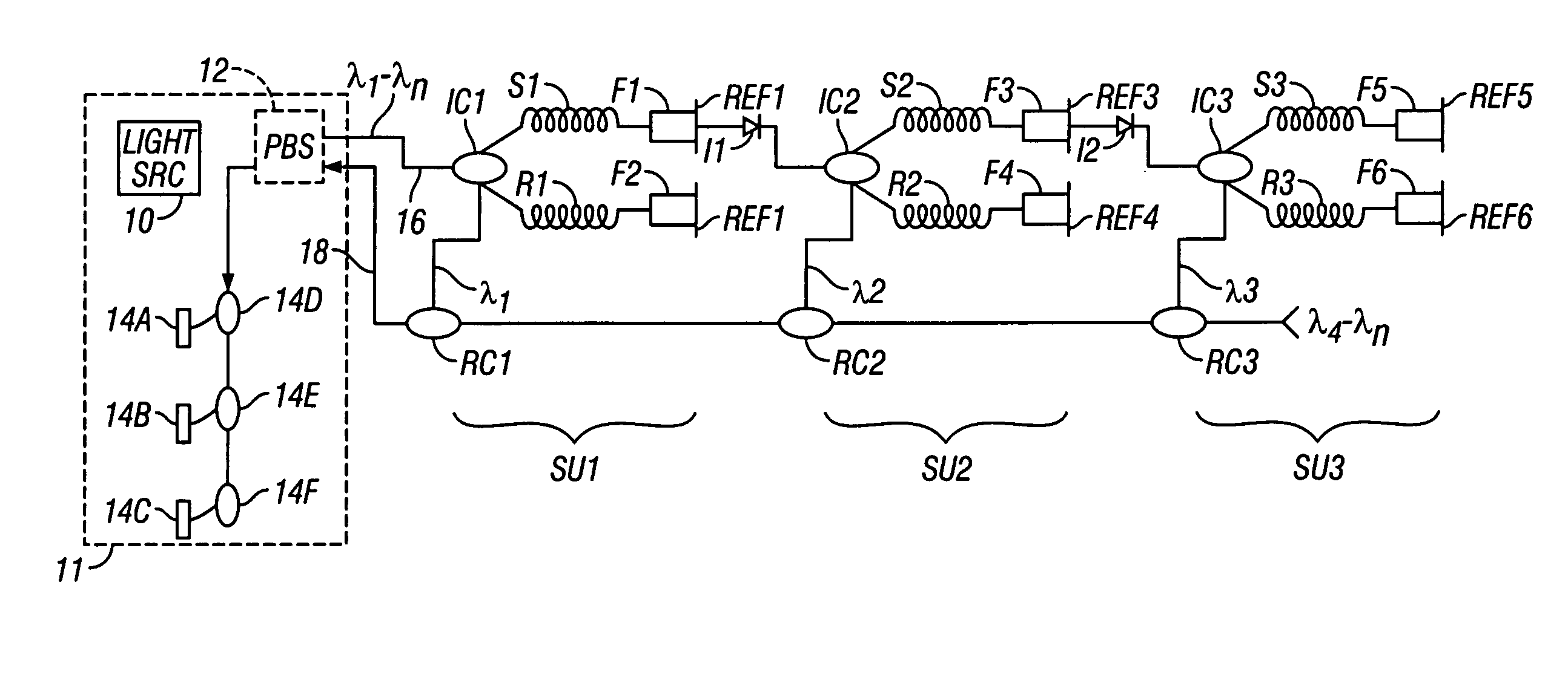
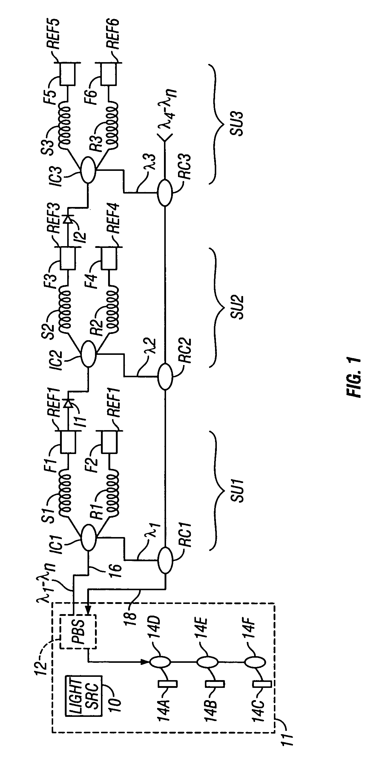
[0021] One embodiment of a fiber optic sensor array and telemetry system is shown schematically in FIG. 1. The system includes a light source / detector module 11. The module 11 includes a light source 10 which may be a plurality of laser diodes, or other type of light source capable of emitting light at a plurality of individual wavelengths λ1-λn for combined output to a light source line 16. The light source line 16 connects to one input of a first optical coupling IC1. The first optical coupling IC1 is a conventional optical coupling including two input terminals, and in this embodiment may include a 10 percent output terminal and a 90 percent output terminal.

[0022] In the present embodiment, the 90 percent output terminal may be coupled to one end of a first sensor fiber S1. The first sensor fiber S1 may be in the form of a coil, and in some implementations may be an acoustic or seismic sensing coil. The 10 percent output terminal may be coupled to a reference fiber R1, which als...


PUM


Abstract

An optical fiber sensor array is disclosed which includes a first sensor fiber and a first reference fiber coupled at one end thereof to one side of a first optical coupling. A first wavelength selective reflector is coupled to the other end of each of the first sensor fiber and the first reference fiber. A second sensor fiber is coupled at one end to one side of a second optical coupling. The other side of the second optical coupling is coupled to an opposite side of one of the first wavelength selective reflectors coupled on one side to the first sensor fiber and the first reference fiber. The array also includes a second wavelength selective reflector coupled to the other end of each of the second sensor fiber and the second reference fiber. The second wavelength selective reflectors are operative at a wavelength different from an operative wavelength of the first wavelength selective reflectors.

Description

CROSS-REFERENCE TO RELATED APPLICATIONS [0001] Not applicable. STATEMENT REGARDING FEDERALLY SPONSORED RESEARCH OR DEVELOPMENT [0002] Not applicable. BACKGROUND OF THE INVENTION [0003] 1. Field of the Invention [0004] The invention relates generally to the field of fiber optic telemetry systems and fiber optic sensor systems. More specifically, the invention relates to wavelength division multiplex telemetry systems for an array of fiber optic sensors. [0005] 2. Background Art [0006] Fiber optic sensors known in the art include an optical fiber sensing element, typically in the form of a coil of optical fiber, that is arranged such that the length and / or the refractive index of the optical fiber sensing element is changed by the action of the physical parameter being measured by the sensor. For example, a fiber optic acoustic sensor has a fiber sensing coil wound around a cylinder, the shape of which changes by the action of a pressure wave, or an acoustic wave, impinging on the cyl...

Claims


Application Information

Patent Timeline
IPC IPC(8): G01J4/00G01J5/08
CPCG01H9/004G01V1/20H04J14/028G01D5/35325H04J14/0227G01D5/35387G01D5/35383G01B9/02041H04J14/0228
Inventor MAAS, STEVEN J.
Owner GEOSPACE TECH
Why Eureka
Try Eureka