Optimized air core armature

a technology of air core and armature, which is applied in the direction of dynamo-electric components, dynamo-electric machines, magnetic circuit shapes/forms/construction, etc., can solve the problems of large flux density reduction and contrary to design principles, and achieves easy manufacturing, increased efficiency and power capability, and reduced armature resistive losses

Inactive Publication Date: 2006-02-23
REVOLUTION ELECTRIC MOTOR
View PDF15 Cites 18 Cited by
  • Summary
  • Abstract
  • Description
  • Claims
  • Application Information

AI Technical Summary

Benefits of technology

[0004] The invention provides a brushless air core motor-generator having an armature with special windings configuration that increases efficiency and power capability with easy manufacturing. The motor-generator is comprised of a rotor that is journalled to rotate about an axis of rotation and a stator that is stationary and magnetically applies torque to the rotor. The rotor comprises magnetic poles that drive magnetic flux across an armature airgap and the stator comprises an air core armature located in the armature airgap and comprising windings such that AC voltage is induced in the windings as the rotor rotates. The windings comprise active length portions that are located in the armature airgap, receive the magnetic flux and induce the AC voltage, and end turn portions that traverse circumferentially and connect together the active length portions. The magnetic poles have a circumferential pole pitch, Y, and the active length portions of the windings have an active length circumferential width of a single phase, X, such that 0.5 Y<X<Y. More preferably, 0.55 Y<X<0.90 Y. Unlike trapezoidal windings wherein X=Y / 3 or full phase layer windings wherein X=Y, the invention provides a unique and unexpected reduction of the armature resistive losses and an increase of the efficiency and power capability of the motor-generator. The result is particularly surprising because the armature has a lower winding density, yet it achieves higher performance. This result is contrary to the design principles that are well known in the art of air core armatures.

Problems solved by technology

This result is contrary to the design principles that are well known in the art of air core armatures.
As a result, the circumferential flux density distribution in the armature airgap suffers from significant circumferential areas near the interfaces between adjacent poles where the flux density is greatly reduced.

Method used


Image

  • Optimized air core armature
  • Optimized air core armature
  • Optimized air core armature

Examples


Embodiment Construction

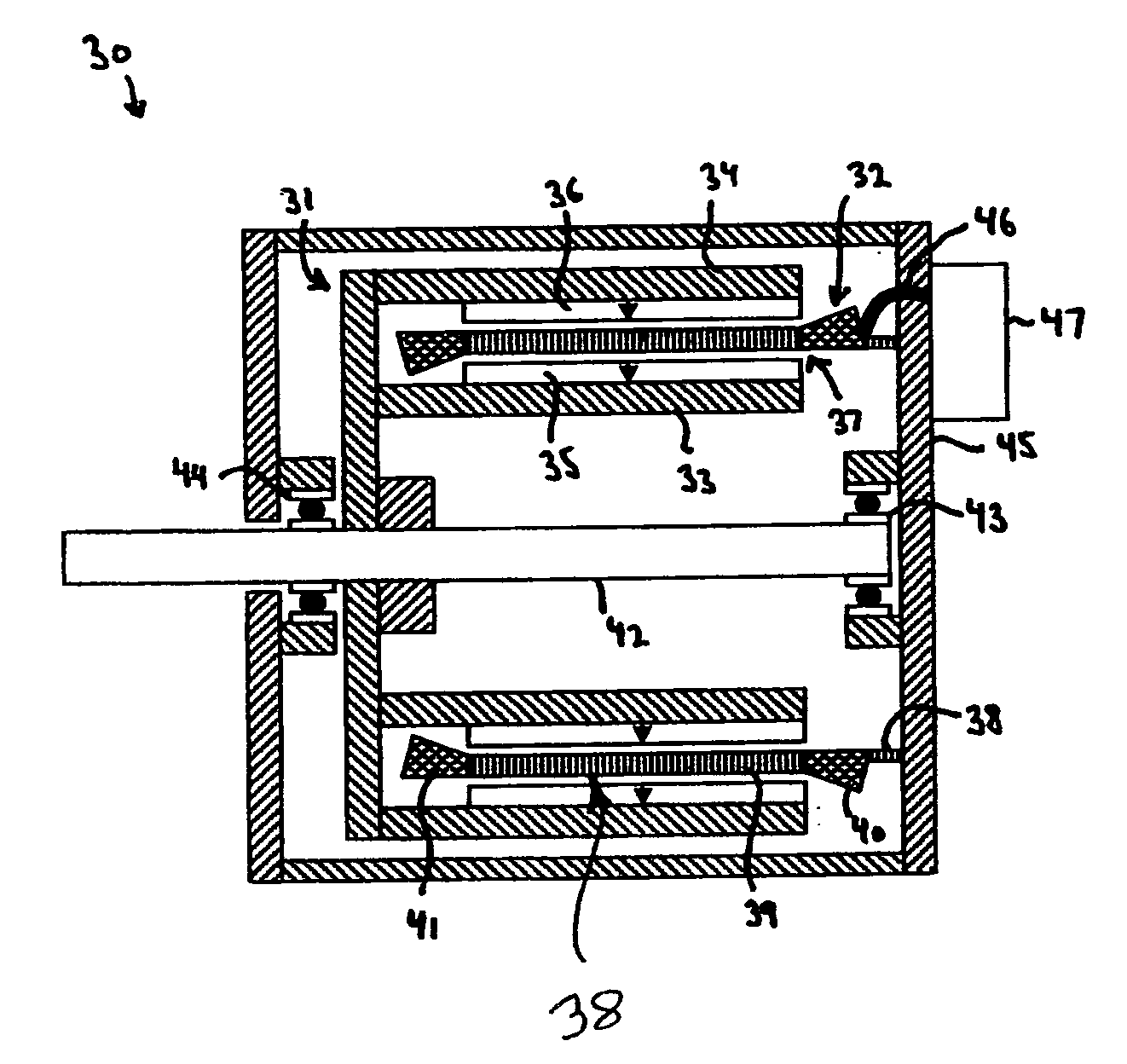
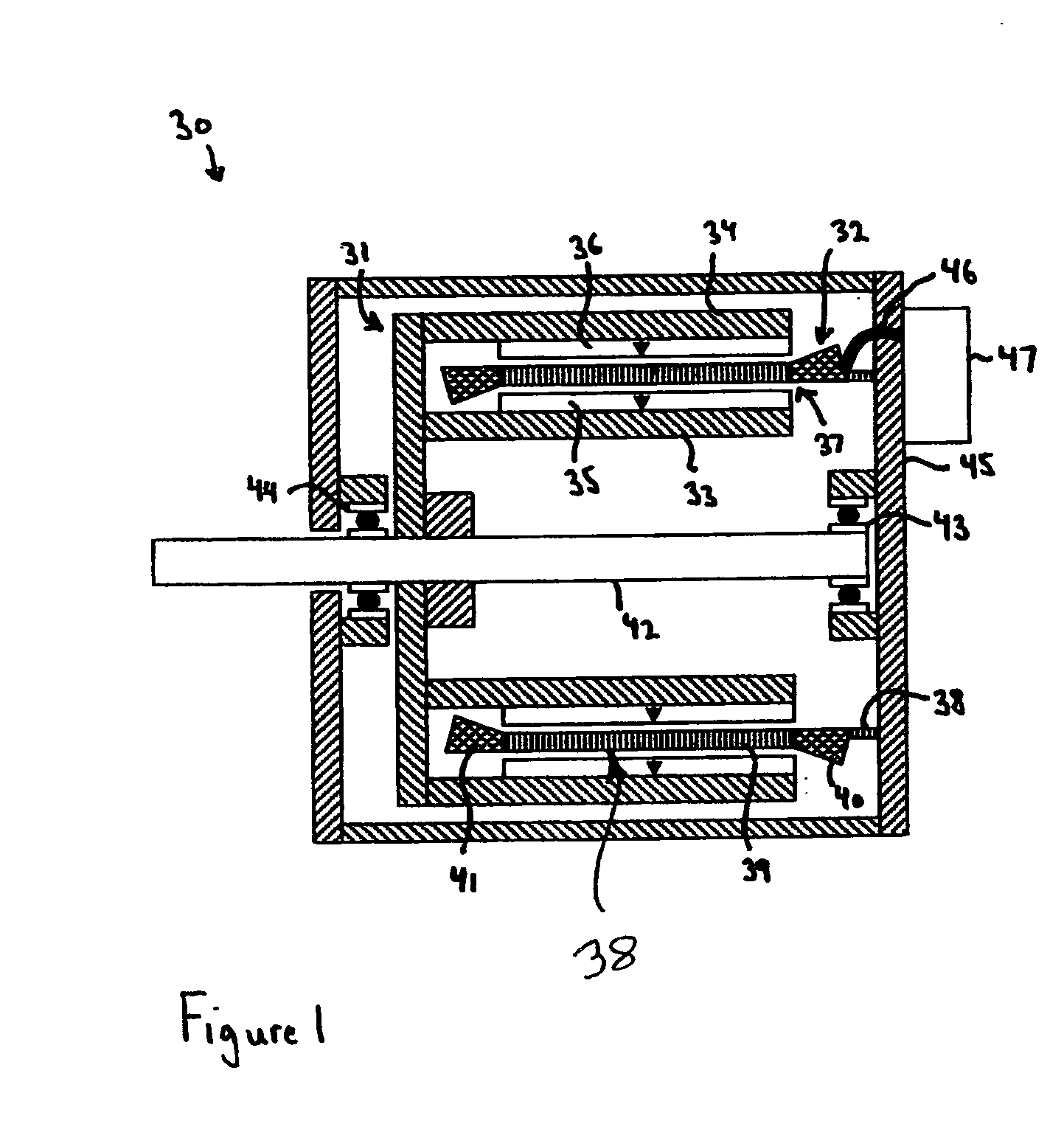
[0025] Turning to the drawings, wherein like reference characters designate identical or corresponding parts, FIG. 1 shows a brushless air core radial gap motor-generator 30 constructed of a rotor 31 mounted for rotation relative to a stationary stator 32. The rotor 31 is comprised of two spaced apart steel tubes 33, 34 to which circumferential arrays of alternating polarity magnets 35, 36 are attached. The magnets 35, 36 drive magnetic flux across the armature magnetic airgap 37 formed within the rotor 31. Located in the magnetic airgap 37 is an air core armature 38 that is comprised of windings having active length portions 39 and end turn portions 40, 41. The active length portions 39 are located in the magnet airgap 37 such that AC voltage is induced in the windings as the rotor 31 rotates. The end turn portions 40, 41 traverse circumferentially and connect together the active length portions 39. The rotor 31 is connected to a shaft 42 that is journalled by bearings 43, 44. The ...


PUM


Abstract

An air core motor-generator has a rotor that is journalled to rotate about an axis of rotation, and a stator that is stationary and magnetically applies torque to the rotor. The rotor has magnetic poles that drive magnetic flux across an armature airgap, and the stator has an air core armature located in the armature airgap. Windings on the armature cause AC voltage to be induced in the windings as the rotor rotates. The windings include active length portions that are located in the armature airgap to receive the magnetic flux and induce the AC voltage, and end turn portions that traverse circumferentially and connect together the active length portions. The magnetic poles have a circumferential pole pitch, Y, and the active length portions of the windings having an active length circumferential width of a single phase, X, such that 0.5 Y<X<Y.

Description

[0001] This invention pertains to brushless motor-generators and more particularly to air core motor-generators that employ a new armature with a special windings configuration that increases the efficiency and power capability while also facilitating easy manufacturing. BACKGROUND OF THE INVENTION [0002] Air core motor-generators have the potential to provide higher efficiency and performance than conventional type electrical machines. They achieve these advantages by eliminating slot wound armature windings wherein the windings are wound in slots in a steel stator, and instead locate the windings within the magnetic airgap. Air core motor-generators can utilize single rotating or double rotating construction. Single rotating construction utilizes a loss mitigating ferromagnetic stator on one side of the airgap. Double rotating air core motor-generators eliminate the need to pass a circumferentially varying flux through a ferromagnetic stator by bounding both sides of the magnetic ...

Claims


Application Information

Patent Timeline
Patent Type & Authority Applications(United States)
IPC IPC(8): H02K21/12H02K1/22H02K16/00
CPCH02K3/47H02K21/24H02K21/14H02K16/02
Inventor GABRYS, CHRISTOPHER W.
Owner REVOLUTION ELECTRIC MOTOR
Why Eureka
Try Eureka