
Azimuth/attitude detecting sensor

a technology of azimuth and attitude, applied in the field of azimuth/attitude detecting sensors, can solve the problems of inability to use practical applications, inability to detect the accuracy of the gyro or accelerometer, etc., and achieves the effect of reducing the error level, simple structure and low cos

Active Publication Date: 2006-02-23
TOKIMEC INC
View PDF6 Cites 63 Cited by
  • Summary
  • Abstract
  • Description
  • Claims
  • Application Information

AI Technical Summary

Benefits of technology

[0020] According to the present invention, under a condition wherein the reliability of the GPS direction signal is high, azimuth error is compensated by using a GPS direction signal and a difference between the GPS direction signal and a magnetic azimuth signal is calculated as well, while under a condition wherein the reliability of the GPS direction signal is not high, instead of using only the magnetic azimuth signal, an azimuth error is compensated by using the difference between the GPS direction signal and magnetic azimuth signal calculated when the reliability of the GPS direction signal is high and the magnetic azimuth signal. Therefore a signal to be referenced does not change drastically between when the reliability of the GPS direction signal is high and when the reliability of the GPS direction signal is not high. Even when there is an influence of a surrounding magnetic field environment, it is possible to reduce the influence thereof and correct azimuth errors more accurately.
[0024] The calculation section for level error compensatory value can remove the motion acceleration from the accelerations of the acceleration signals using a GPS velocity signal output from the GPS receiver and calculates the level error compensatory value. Since the GPS velocity obtained by the GPS receiver is used to remove influences of the motion acceleration for the acceleration detected by the accelerometer, it is possible to correct the level error in a simple structure and at low cost.

Problems solved by technology

However, the accelerometers also detect motion acceleration other than gravity, and therefore a problem is that an attitude error occurs under the influence of motion acceleration.
Using costly and high-performance gyros and accelerometers allow an azimuth / attitude detecting sensor less susceptible to motion acceleration to be constructed, but the influence of the motion acceleration when a low cost, low precision gyro or accelerometer is used is considerable and a problem is that they are unusable for practical applications depending on the motion state.
When a mobile unit performs turning motion, the mobile unit which cannot bear a centrifugal force occured during the turning motion, produces a side slipping which causes the velocity in the traveling direction not to match the actual trajectory velocity.
The side slipping produces an error of the angles of attitude because only the velocity in the X-axis direction can be detected and an acceleration component due to the velocity in the Y-axis direction cannot be compensated.
However, such a calculation described in Japanese Patent Laid-Open No. 6-201863 requires a velocimeter and also requires a calculation apparatus calculating the angle of side slipping, resulting in a problem that the size and cost of the apparatus increase.
Moreover, since the azimuth detected by the geomagnetism sensor is unconditionally assumed to be the traveling azimuth, a problem is that in the case of a motion state in which the traveling direction differs from the axial direction of the magnetic azimuth sensor, a wrong direction may be assumed to be the traveling direction.
However, in Japanese Patent Laid-Open No. 2002-158525, when the reference value changes from the absolute azimuth detected by the magnetic compass to the traveling direction azimuth detected by the GPS receiver depending on change of the condition, which produces a problem that the reference value changes drastically and it lacks reliability as a reference value.

Method used


Image

  • Azimuth/attitude detecting sensor
  • Azimuth/attitude detecting sensor
  • Azimuth/attitude detecting sensor

Examples


Embodiment Construction

[0031] With reference now to the attached drawings, an embodiment of the present invention will be explained below.

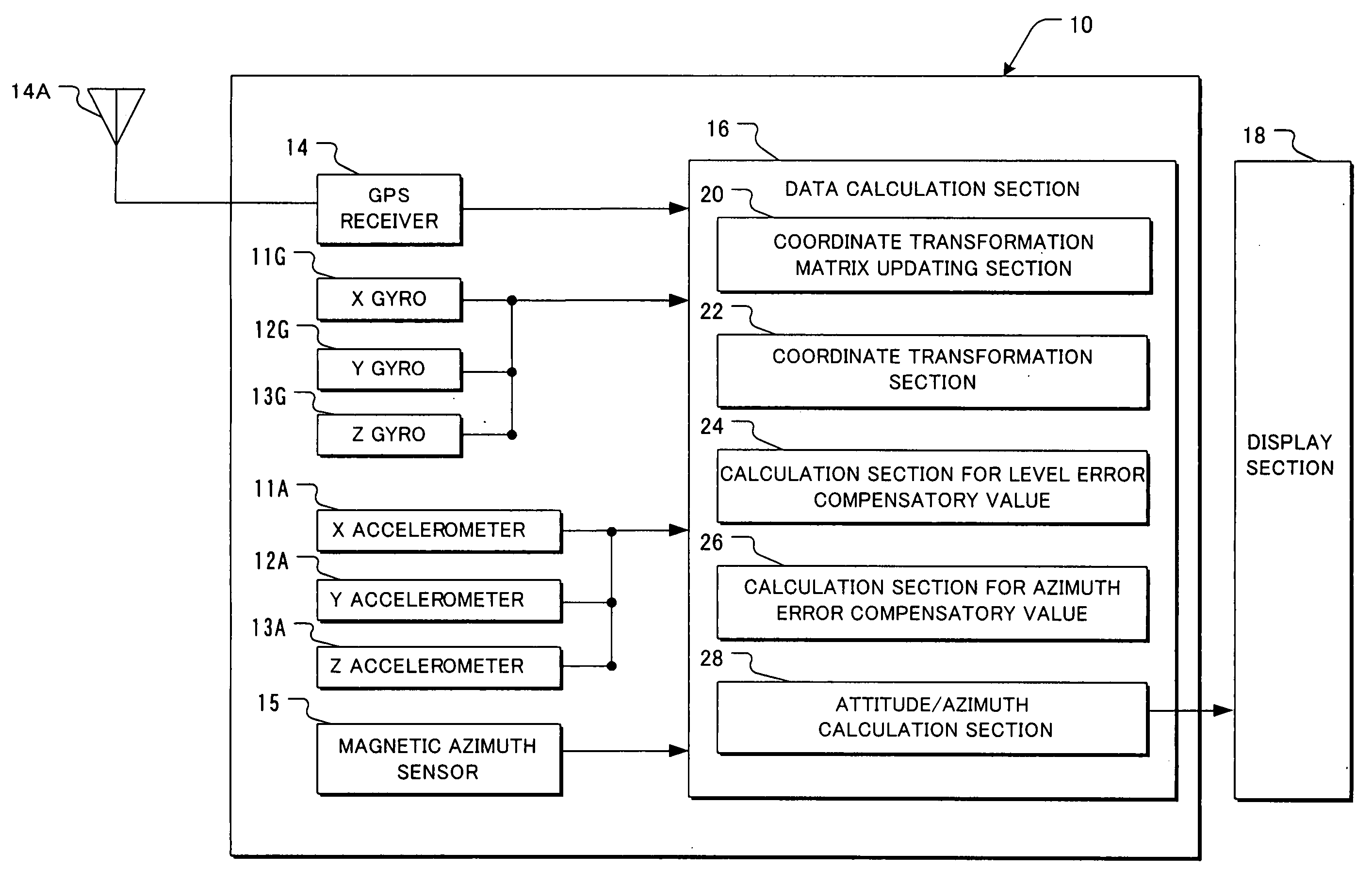
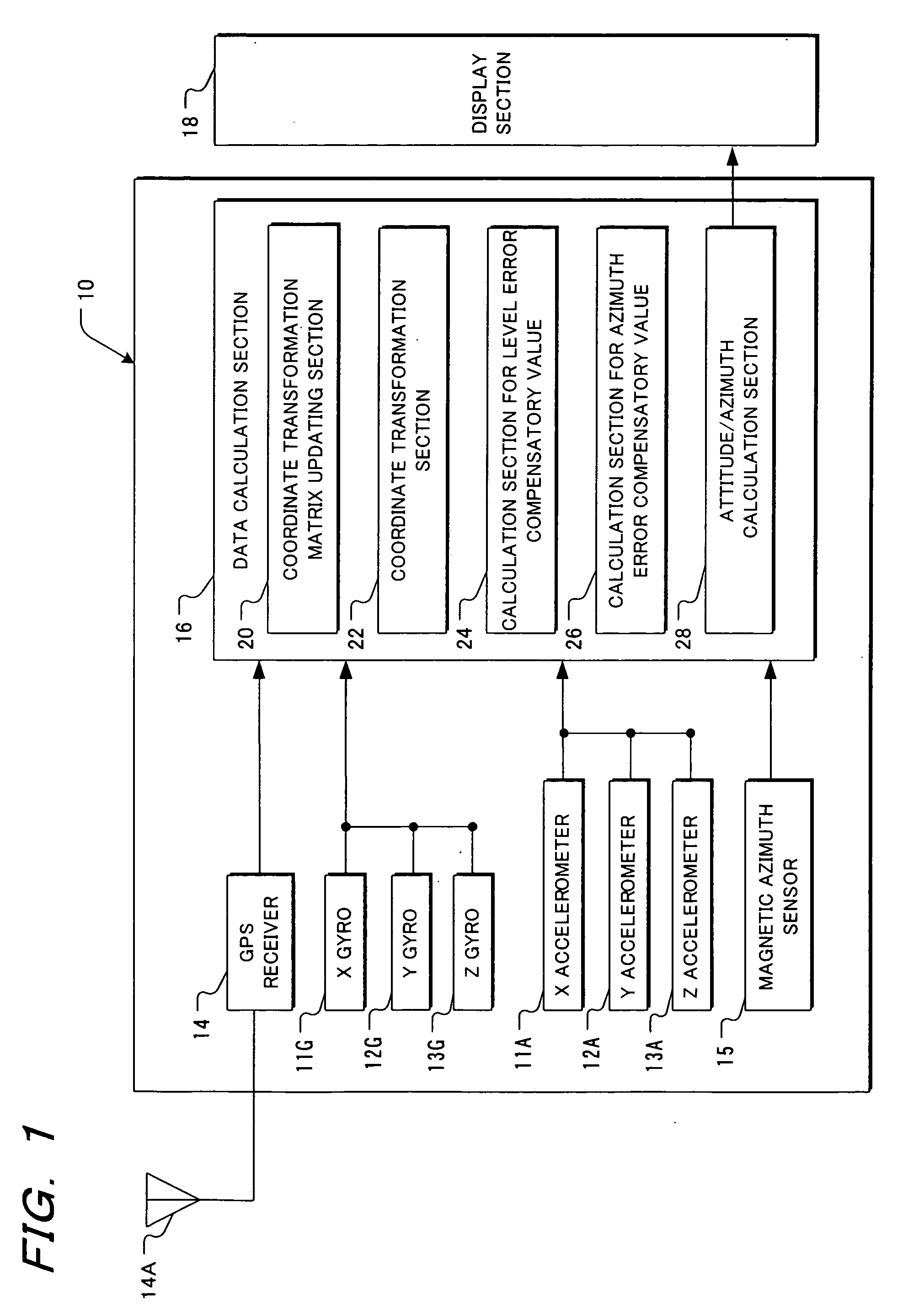
[0032]FIG. 1 is a block diagram of an azimuth / attitude detecting sensor according to an embodiment of the present invention. The azimuth / attitude detecting sensor 10 is provided with an X gyro 11G which detects an angular velocity around the X-axis, a Y gyro 12G which detects an angular velocity around the Y-axis, a Z gyro 13G which detects an angular velocity around the Z-axis, an X accelerometer 11A which detects acceleration in the X-axis direction, a Y accelerometer 12A which detects acceleration in the Y-axis direction, a Z accelerometer 13A which detects acceleration in the Z-axis direction, a GPS antenna 14A, a GPS receiver 14 connected to the GPS antenna 14A, a magnetic azimuth sensor 15, and a data calculation section 16 configured by a control section including a CPU, ROM and RAM. The sensor 10 can be connected with a display section 18. The X gyro 11G, Y gyr...


PUM


Abstract

The sensor successively calculates a rolling angle, pitch angle and azimuth from the coordinate transformation matrix with the level error and azimuth error compensated. It calculates azimuth error compensatory values using the GPS direction signal and calculates a difference between the GPS direction signal and magnetic azimuth signal under a condition wherein the reliability of the GPS direction signal is high, whereas it calculates azimuth error compensatory values using the calculated difference between the GPS direction signal and magnetic azimuth signal and the magnetic azimuth signal under a condition wherein the reliability of the GPS direction signal is not high and under a condition wherein the reliability of the magnetic azimuth signal is not low.

Description

BACKGROUND OF THE INVENTION [0001] 1. Field of the Invention [0002] The present invention relates to an azimuth / attitude detecting sensor according to a strap-down system, which detects an azimuth / attitude of a mobile unit such as a ship or car. [0003] 2. Description of the Related Art [0004] Conventionally, an azimuth / attitude detecting sensor according to a strap-down system includes X, Y and Z accelerometers which detect accelerations in respective axial directions and X, Y and Z gyros which detect angular velocities around respective axes (see Japanese Patent No. 3038452). [0005] This azimuth / attitude detecting sensor uses gyro signals obtained from the gyros to calculate a matrix for transforming a coordinate system of a body to which a sensor is attached (called a “body coordinate system”) to a coordinate system in which the X-axis direction corresponds to the north direction and the Z-axis direction coincides with the gravity direction (called a “local coordinate system”), ca...

Claims


Application Information

Patent Timeline
IPC IPC(8): G01S5/14G01S19/49G01C21/00
CPCG01C21/165G01S19/53G01S19/40G01C21/1654
Inventor ARAKANE, HIROOMIOKAMURA, NOBUYUKISAGAWA, TAKAO
Owner TOKIMEC INC
Features
  • Generate Ideas
  • Intellectual Property
  • Life Sciences
  • Materials
  • Tech Scout
  • Unparalleled Data Quality
  • Higher Quality Content
  • 60% Fewer Hallucinations
Learn More