

Parallel loop antennas for a mobile electronic device
- Summary
- Abstract
- Description
- Claims
- Application Information
AI Technical Summary
Benefits of technology
Problems solved by technology
Method used
Image

Examples
example electronic
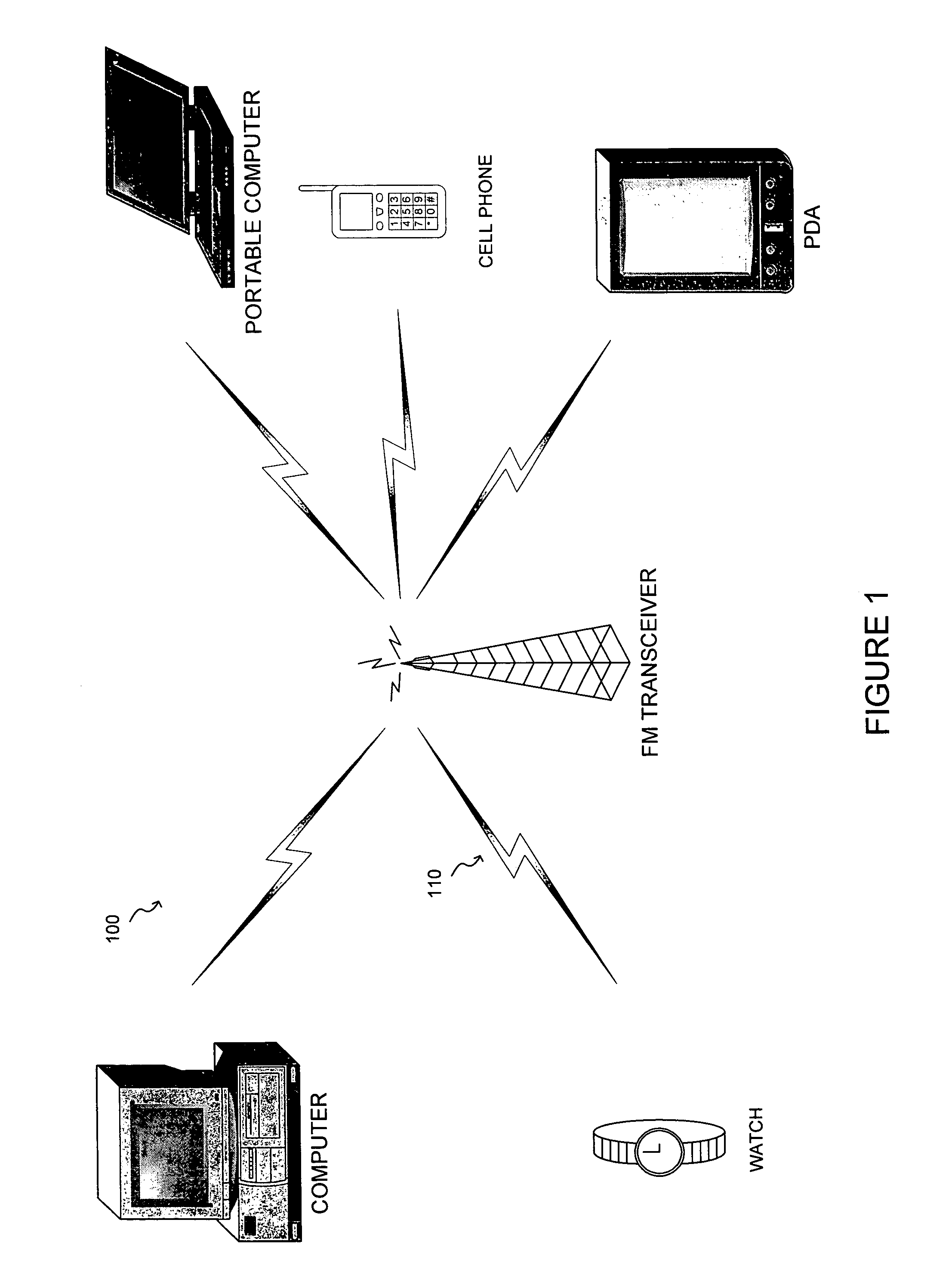
[0030] Example electronic devices that may include an electronic system that is arranged to operate according to the interaction model are illustrated in FIG. 1. The electronic system may employ a wireless interface such as the FM transmission systems that are described above. Each of the electronic systems receives messages / information over the communication channel.
[0031] The operating environment shown and described are only examples of suitable operating environments and are not intended to suggest any limitation as to the scope of use or functionality of the invention. Other well known computing systems, environments, and / or configurations that may be suitable for use with the invention include, but are not limited to, personal computers, server computers, hand-held or laptop devices, multiprocessor systems, microprocessor-based systems, programmable consumer electronics, network PCs, minicomputers, mainframe computers, distributed computing environments that include any of the...
PUM
 Abstract
Description
Claims
Application Information