Electrochemical cell

a technology of electrochemical cells and liquid leakage, applied in the direction of secondary cells, cell components, sustainable manufacturing/processing, etc., can solve the problems of high cost, high time and high cost, and achieve the effect of low cost, high cost and high tim

Inactive Publication Date: 2006-02-23
SEIKO INSTR INC
View PDF6 Cites 50 Cited by
  • Summary
  • Abstract
  • Description
  • Claims
  • Application Information

AI Technical Summary

Benefits of technology

[0014] In the conventional electrochemical cell in which the cap has the same size as the container, the inspection was necessary from four sides, and much time and high cost were required, however, in the electrochemical cell of the invention, the observation is necessary only from a top face of the electrochemical cell when it is inspected for liquid leakage.
[0015] Moreover, even in a configuration where a metal ring is provided between the container and the cap, it is possi

Problems solved by technology

Much time and high cost have been required for examining presence of liquid leakage in the electrochemical cell.
However, in the conventional electrochemical cell, since the outer circumference of the

Method used


Image

  • Electrochemical cell
  • Electrochemical cell
  • Electrochemical cell

Examples


example 1

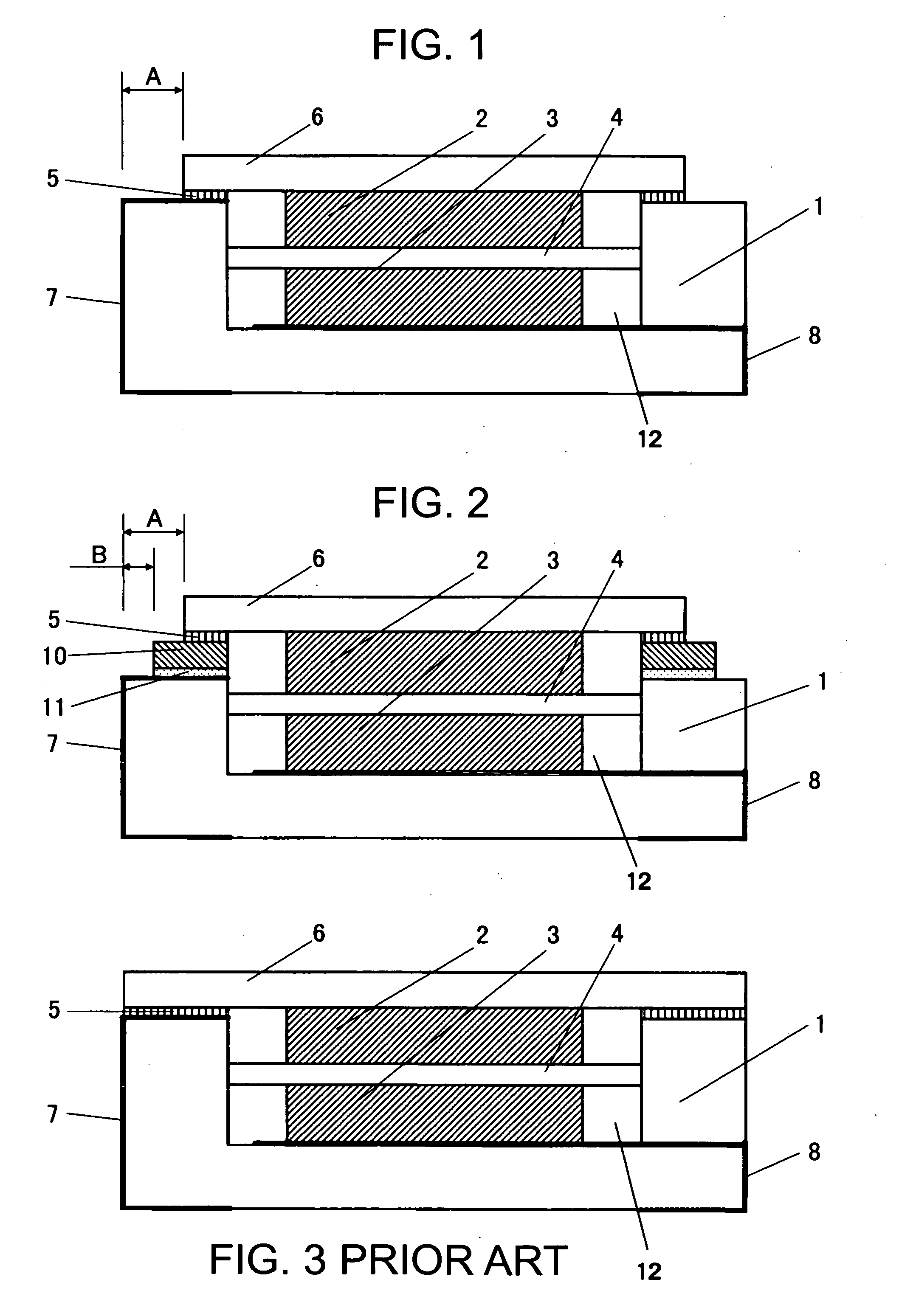
[0033] A nonaqueous-electrolyte secondary battery as shown in FIG. 1 was made. A box-type container 1 was formed by stacking two layers of ceramic sheets and a cathode terminal 8 was formed between them. An anode terminal 7 was formed along a side of the container from a bottom of the container 1 such that it electrically contacted to the bonding material 5. The container 1 was made to have a size of 5×3×0.9 mm, and the bonding material 5 comprising an AgCu alloy was formed on a top face of an outer wall of the container.

[0034] Commercially available molybdenum trioxide, graphite, and polyacrylic acid were mixed in a ratio of 50 / 45 / 5 in a percent by weight, and then formed into a molding by press at a pressure of 2 T / cm2 and used as a cathode 3. An anode 2 was made by mixing commercially available silicon monoxide, graphite, and polyacrylic acid in a ratio of 45 / 40 / 15 in a percent by weight, and then forming into a molding by press at a pressure of 2 T / cm21 and then applying not-sh...

example 2

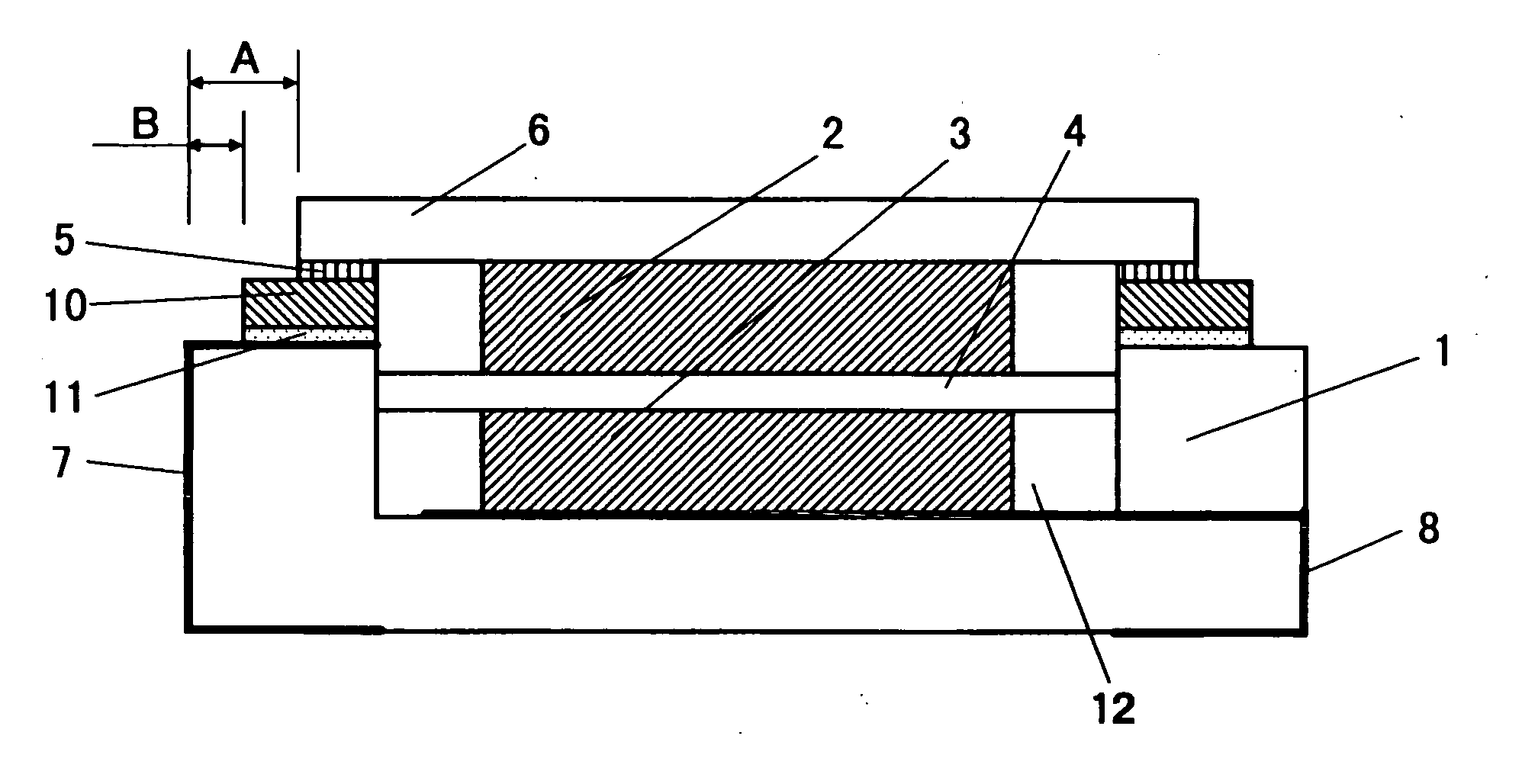
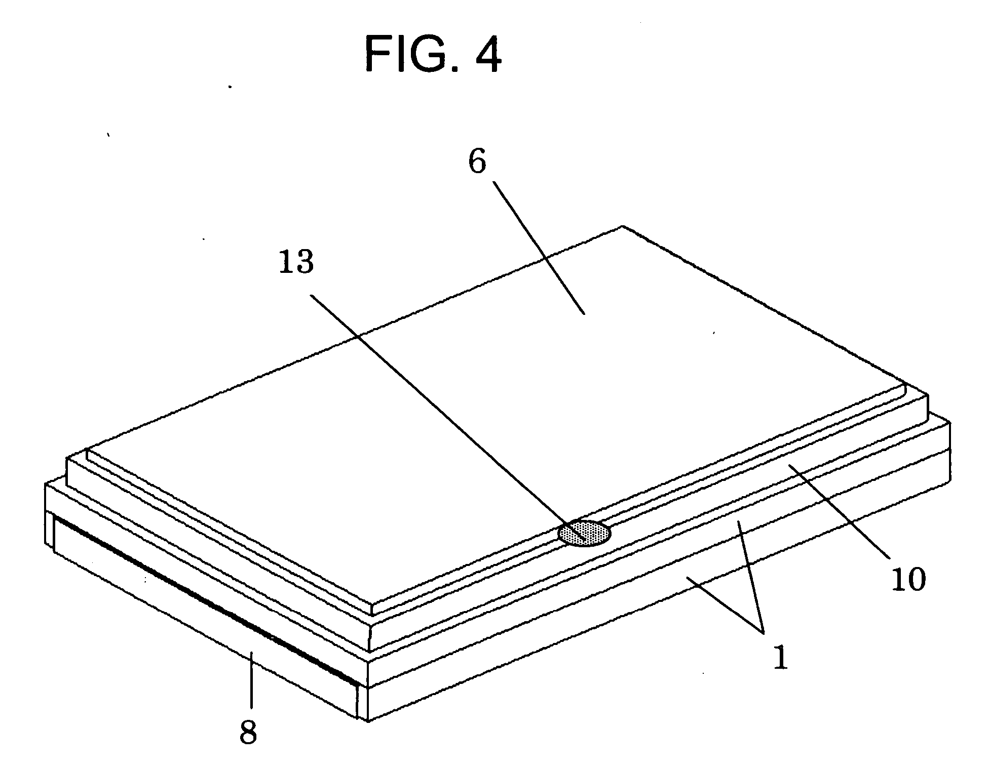
[0038] An electric double layer capacitor as shown in FIG. 2 was made. A box-type container 1 was formed by stacking two layers of ceramic sheets, and a cathode terminal 8 was formed between them. An anode terminal 7 was formed along a side of the container from a bottom of the container 1 such that it electrically contacted to the bonding material 11. The container 1 was made to have a size of 5×3×0.7 mm, and the bonding material 11 comprising an AgCu alloy was formed on a part of the container. After that, a metal ring 10, which comprises a FeNiCo alloy, having a peripheral size of 4.8×2.8×0.2 mm was placed on the bonding material 11 and then bonded to the material by heating. After that, Ni plating was applied on surfaces of the bonding material 11 and the metal ring 10, and then Au plating was applied thereon, which was used as a bonding material 5.

[0039] Commercially available activated carbon, graphite, and polytetrafluoroethylene were mixed in a ratio of 90 / 5 / 5 in a percent ...


PUM

PropertyMeasurementUnit
Circumferenceaaaaaaaaaa

Abstract

In an electrochemical cell in which a container is bonded to a cap, observation of liquid leakage has been needed in directions from four sides of the container, therefore much time and high cost have been required. The outer circumference of the cap is made to be smaller than that of the container, whereby surfaces for observing liquid leakage can be made to be only one surface in a direction from an upside of the cap, consequently an electrochemical cell can be provided at low cost.

Description

BACKGROUND OF THE INVENTION [0001] 1. Field of the Invention [0002] The present invention relates to an electrochemical cell such as nonaqueous-electrolyte secondary battery or electric double layer capacitor. [0003] 2. Description of the Related Art [0004] The electrochemical cell such as nonaqueous-electrolyte secondary battery or electric double layer capacitor, having features of high energy density, lightweight, and small size, has been used for a backup power source for a clock function of mobile devices or a backup power source for a semiconductor memory. The mobile devices are needed to have smaller size and lighter weight, and have improved performance, and further high density package of the electrochemical cell is required. [0005] When the electrochemical cell is mounted on a circuit board, reflow soldering is generally used. The reflow soldering is a soldering method by applying a soldering cream on an area to be soldered in the circuit board, and then placing the electr...

Claims


Application Information

Patent Timeline
IPC IPC(8): H01M2/08H01M10/04H01G9/00H01G9/08H01G11/00H01G11/24H01G11/26H01G11/38H01G11/42H01G11/54H01G11/56H01G11/78H01G11/84H01G11/86H01M10/05H01M10/0565H01M10/0566H01M50/186H01M50/548H01M50/553
CPCH01G9/08H01M2/021H01M2/08Y10T29/49114H01M10/052H01M10/4228Y02E60/13H01M10/0436Y02E60/10Y02P70/50H01M50/553H01M50/186H01M50/548
Inventor ONODERA, HIDEHARUKIDA, TOMOHIKOWATANABE, SHUNJITAHARA, KENSUKE
Owner SEIKO INSTR INC
Why Eureka
Try Eureka