
System and method for zero latency distributed processing of timed pyrotechnic events

a distributed processing and timed technology, applied in the field of pyrotechnic and explosive control systems, can solve the problems of delay in timing of operation, delay in operation, delay in latency, etc., and achieve the effect of optimizing the amount of energy delivered and zero latency

Active Publication Date: 2006-03-02
BIRKET IP HLDG INC
View PDF4 Cites 16 Cited by
  • Summary
  • Abstract
  • Description
  • Claims
  • Application Information

AI Technical Summary

Benefits of technology

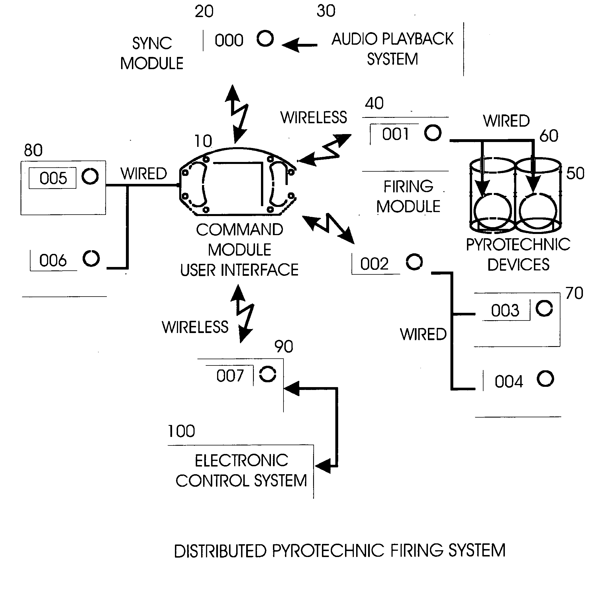
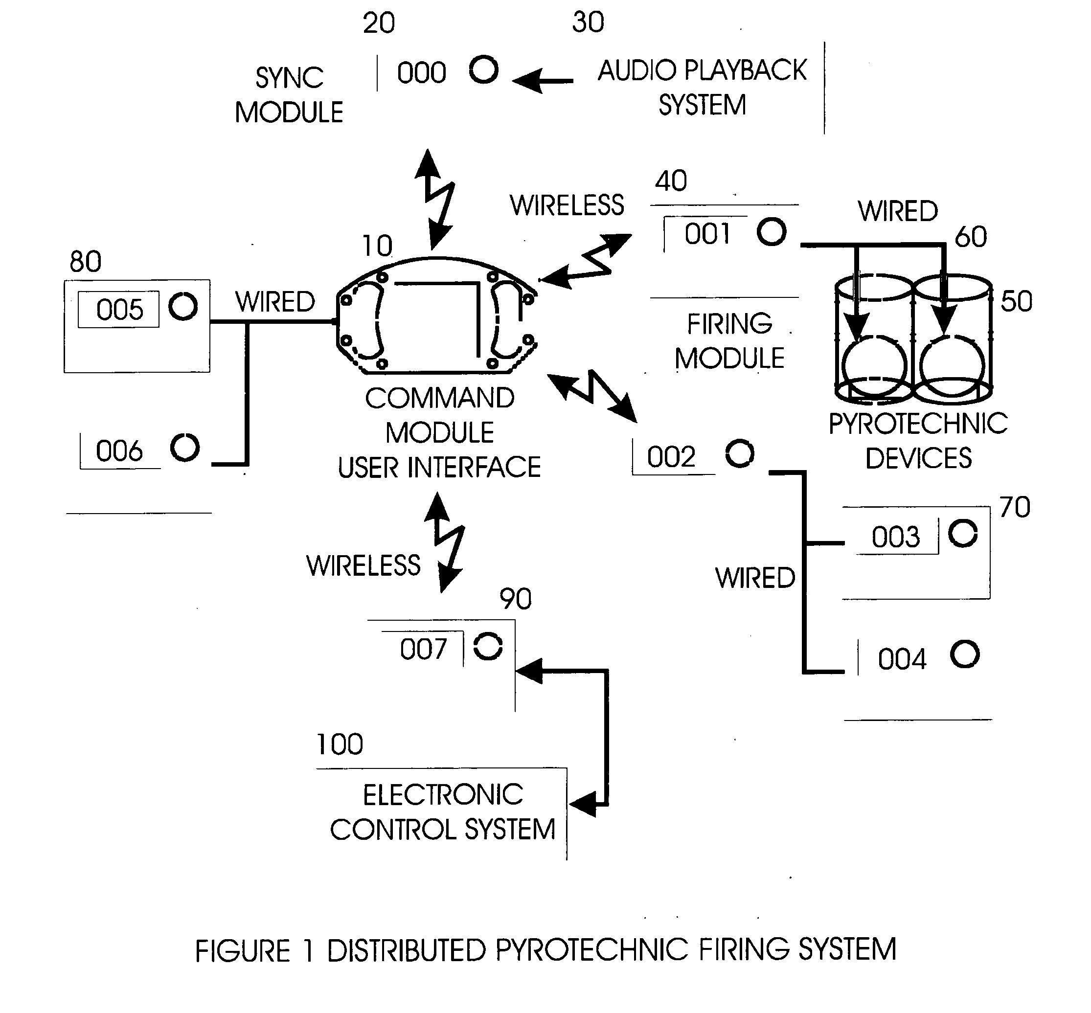
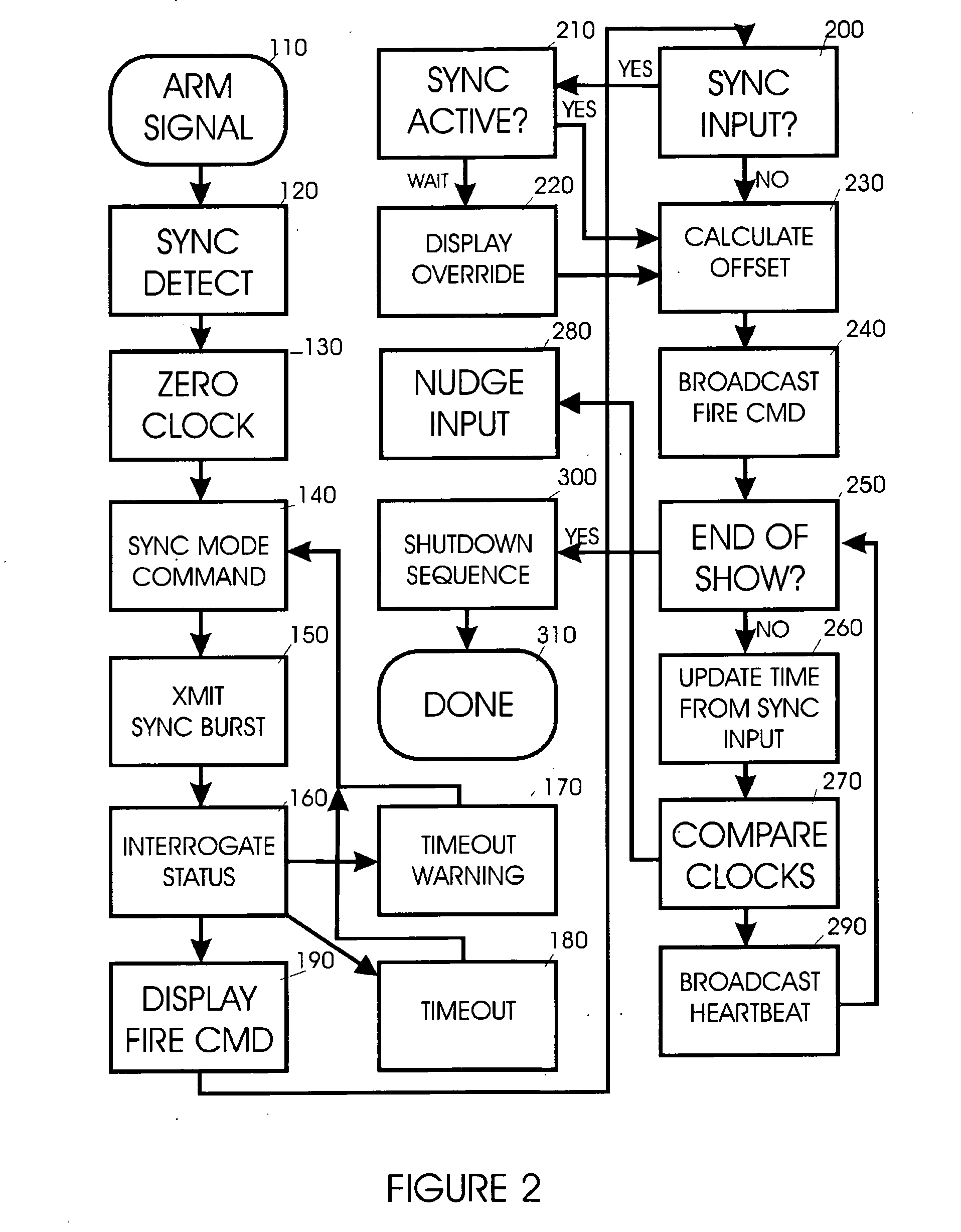
"The patent describes a system for processing timed pyrotechnic events using a distributed processor system. The system includes multiple Firing Modules and a Command Module. The Firing Modules synchronize with a master clock and receive and execute commands from the Command Module. This system allows for more timing events to be processed simultaneously while alleviating problems such as wireless radio interference delays. The system also allows for zero latency from the synchronized clock and optimizes the amount of energy delivered to the effector. The technical effects of this system include improved processing speed and accuracy, reduced latency, and improved energy delivery."

Problems solved by technology

A problem with existing pyrotechnic controls is that most pyrotechnic controllers operate in a master-slave architecture.
Unfortunately, this only works in a master-slave environment or when all devices that must interpret events have access to the timing stream or signal.
This same problem occurs when an explicit timing signal such as SMPTE timing track is used to initiate the events.
If more than one match or sets of matches (cues) must be fired simultaneously, there is often a delay as the master firing panel must initiate separate communication or electrical events.
This results in delays and latency as each initiator is fired sequentially.
In addition, if wireless communication is employed between the master controller and slave devices, which perform the switching function, radio interference can cause significant delays in each transmitted packet further delaying the timing of the operation.
These delays seriously disrupt the critical synchronicity of the music and pyrotechnic effect reducing the enjoyment of the audience.
These delays seriously degrade this effect producing uneven firing patterns.
In blasting operations, resonance effects require precise timing between initiator events, which would be critically destabilized by these delays and rendered ineffective.
Similarly, in special effects work, the pyrotechnic event is often synchronized to sound or visual effects, and any delay in the firing would detract from the realism the operator is trying to achieve.
Another problem with conventional pyrotechnic controls is that existing controllers operate on a fixed voltage, current, and time specification.
While this specification might be fine for most series wired electric matches, more time might be required if the matches are wired in parallel or inferior match production causes them to require more than 12.5 mS for ignition.
Existing systems do not have the capability to automatically vary all of these parameters.
Yet another problem with the existing art is when wireless links are employed, a phenomenon known as shadowing occurs.
When an object larger than the wavelength of the radio signal exists between the line-of-sight path of the transmitter and receiver, the signal may be seriously diminished or blocked completely.
Existing systems do not have the ability to maintain contact with a diverse array of receivers when the transmitter moves.
While the foregoing devices may be suitable for the particular purpose to which they address, they are generally not as suitable for creating a firing system where zero latency, accurate timing, flexible output, and operator movement must be achieved.

Method used


Image

  • System and method for zero latency distributed processing of timed pyrotechnic events
  • System and method for zero latency distributed processing of timed pyrotechnic events
  • System and method for zero latency distributed processing of timed pyrotechnic events

Examples


Embodiment Construction

[0026] The present invention is best understood by reference to the detailed figures and description set forth herein.

[0027] Detailed descriptions of the preferred embodiments are provided herein. It is to be understood, however, that the present invention may be embodied in various forms. Therefore, specific details disclosed herein are not to be interpreted as limiting, but rather as a basis for the claims and as a representative basis for teaching one skilled in the art to employ the present invention in virtually any appropriately detailed system, structure or manner.

[0028] One aspect of the present invention is to provide a new method for distributed processing of timed pyrotechnic events that has many of the advantages of the pyrotechnic controls mentioned heretofore and many novel features that result in a new method for distributed processing of timed pyrotechnic events.

[0029] In the description below the term “zero latency” is used, and should be understood to mean that ...


PUM


Abstract

A method for achieving zero, or near zero, latency timed pyrotechnic events by utilizing distributed processing is presented. A list of timed events may be used to synchronize a pyrotechnic firing sequence with music or other external events. This list is distributed over a series of embedded microprocessors. Each microprocessor is then synchronized to a master controller clock, and enabled such that each processor may then fire independently as required by the master list. This distributed process removes the split-second timing requirement from the main controller enabling the achievement of zero latency and providing significantly more timing events to be processed simultaneously while alleviating problems such as wireless radio interference delays. Each module is capable of forwarding information to other modules, which may be a position that prevents wireless communication directly with the master controller.

Description

CROSS-REFERENCE TO RELATED APPLICATIONS [0001] The present Utility patent application claims priority benefit of the U.S. provisional application for patent No. 60 / 605,422 dated Aug. 30, 2004 “Method for distributed processing of pyrotechnic events” under 35 U.S.C. 119(e). The contents of this related provisional application are incorporated herein by reference.FEDERALLY SPONSORED RESEARCH OR DEVELOPMENT [0002] Not applicable. REFERENCE TO SEQUENCE LISTING, A TABLE, OR A COMPUTER LISTING APPENDIX [0003] Not applicable. FIELD OF THE INVENTION [0004] The present invention relates generally to pyrotechnic and explosive control systems in fireworks displays, special effects, and blasting industries. BACKGROUND OF THE INVENTION [0005] It can be appreciated that pyrotechnic controls have been in use for years. Typically, pyrotechnic controls are comprised of electrical firing systems that rely on switches or contact closure thrown by the operator or contact closures initiated by computer ...

Claims


Application Information

Patent Timeline
Patent Type & Authority Applications(United States)
IPC IPC(8): F42C11/00
CPCF42D1/05
Inventor RUSSELL, DAVID WAYNE
Owner BIRKET IP HLDG INC
Learn More