Plasma treatment apparatus, method of producing reaction vessel for plasma generation, and plasma treatment method

a technology of plasma treatment apparatus and reaction vessel, which is applied in the field of plasma treatment apparatus and method, can solve the problems of easy variation of treatment effect on objects, increase in running cost, etc., and achieve the effects of increasing the treatment area, small gas consumption, and high degree of freedom in design

Inactive Publication Date: 2006-03-02
MATSUSHITA ELECTRIC WORKS LTD
View PDF14 Cites 132 Cited by
  • Summary
  • Abstract
  • Description
  • Claims
  • Application Information

AI Technical Summary

Benefits of technology

[0006] In consideration of the above problems, a primary concern of the present invention is to provide a plasma treatment apparatus with a high level of freedom in designing the apparatus depending on the object to be treated, which has the capability of increasing a treatment area and performing a uniform treatment with a small consumption of a gas, i.e., a low running cost.

Problems solved by technology

In this plasma surface treatment, since the plasma or activated species of the plasma is ejected from a single nozzle, and the objects are plasma treated, while being conveyed in a direction orthogonal to the ejecting direction, there is a problem that variations in treatment effect on the objects easily occur.
In addition, such a large-area plasma treatment has another problem that a large amount of consumption of the gas leads to an increase in running cost.

Method used


Image

  • Plasma treatment apparatus, method of producing reaction vessel for plasma generation, and plasma treatment method
  • Plasma treatment apparatus, method of producing reaction vessel for plasma generation, and plasma treatment method
  • Plasma treatment apparatus, method of producing reaction vessel for plasma generation, and plasma treatment method

Examples


example 1

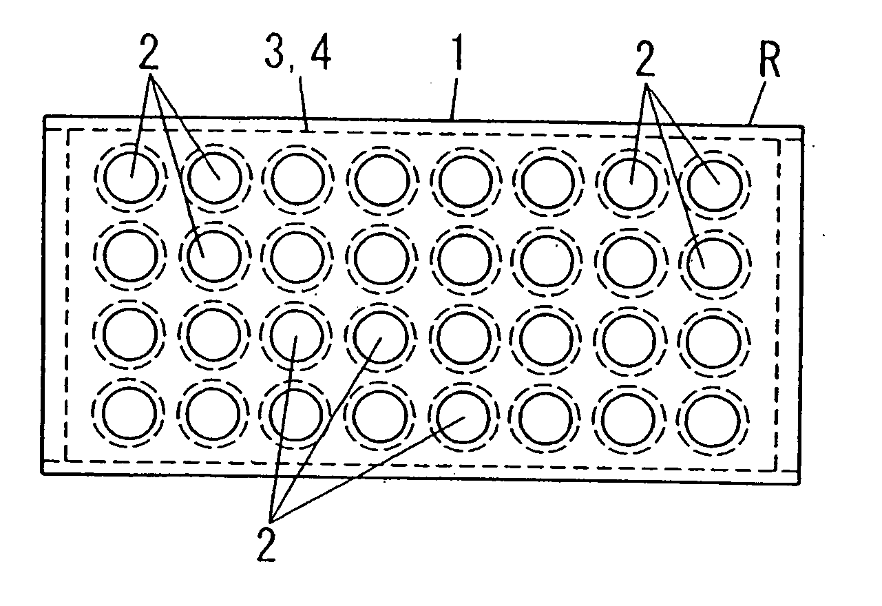
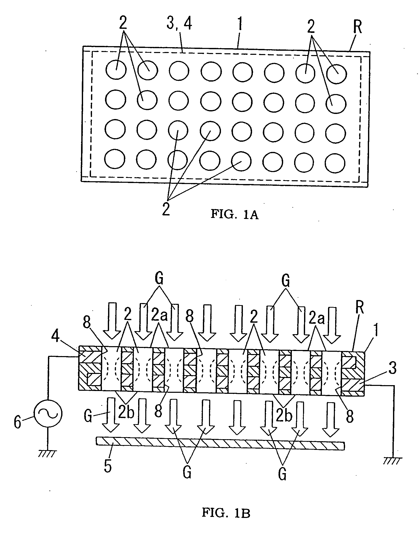
[0122] An electrically conductive film was formed on a surface of a first sheet (thickness: 0.4 mm) by printing, and then a second sheet (thickness: 1.4 mm) was placed on this electrically conductive film. In addition, an electrically conductive film was formed on a surface of the second sheet by printing, and then a third sheet (thickness: 1.4 mm) was placed on this electrically conductive film. In this embodiment, each of the first to third sheets was obtained by molding a material containing an alumina powder into a sheet shape. Each of the sheets has a plurality of apertures each having a diameter of 1 mm. These sheets were disposed in layers such that positions of the apertures of the respective sheets corresponds to each other. The electrically conductive film was formed by printing a tungsten layer. A plurality of apertures 8 each having a diameter of 3 mm larger than the aperture of the sheets were formed in the electrically conductive film such that each of the apertures of...

example 2

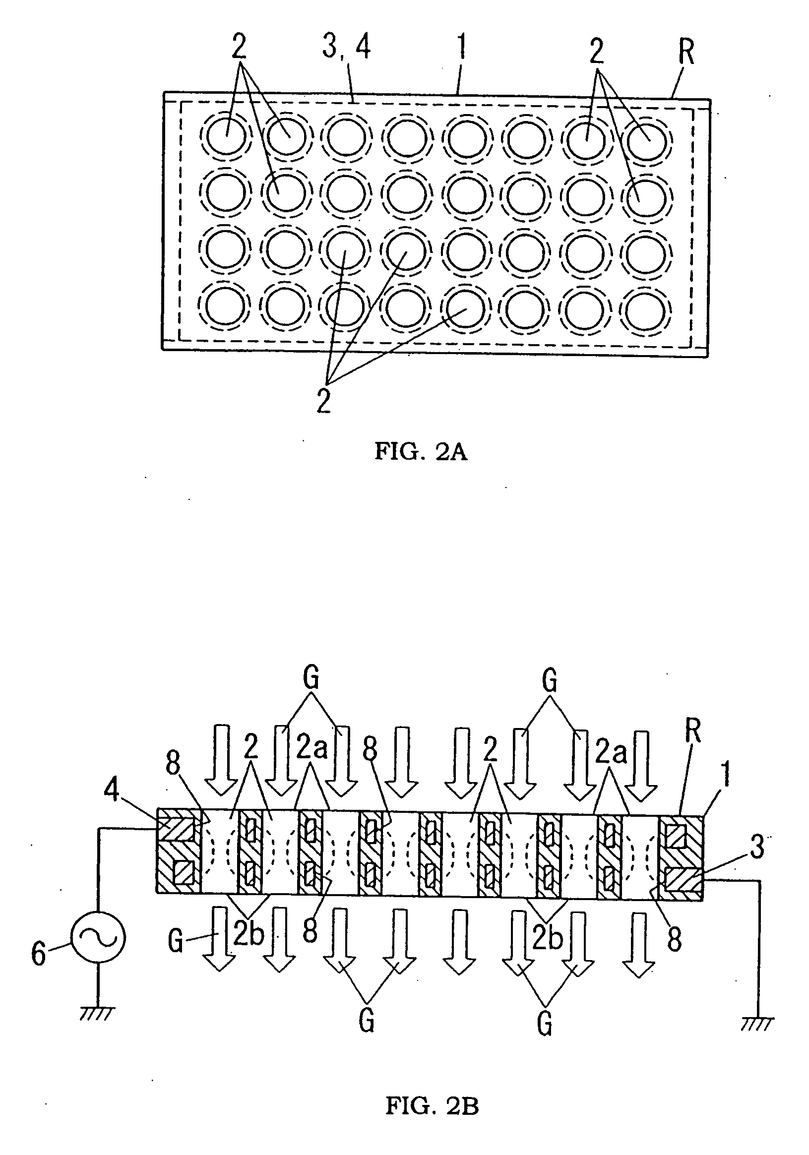
[0125] An electrically conductive film was formed on a surface of a first sheet (thickness: 0.7 mm) by printing, and then a second sheet (thickness: 1.5 mm) was placed on the electrically conductive film. Each of the first and second sheets was formed by molding the material containing alumina into a sheet shape, as in the case of Example 1. Each of the first and second sheets has a plurality of slit-like apertures each having a width of 1 mm and a length of 22 mm in a plan view thereof. These sheets were disposed in layers such that positions of the slit-like apertures of the respective sheets corresponds to each other. The electrically conductive film was formed by printing a tungsten layer, as in the case of Example 1. In this embodiment, each of the electrically conductive films was formed in a comb-shaped pattern. The thus obtained laminate was sintered to obtain a reaction vessel R having a structure shown in FIGS. 3A and 3B.

[0126] In this embodiment, an insulting member 1 of...

example 3

[0128] A plasma treatment apparatus used in this embodiment is substantially the same as the apparatus of Example 1 except that the diameters of the apertures 8 of the electrodes 3, 4 and the through holes 2 are 1 mm, and inner surfaces of the apertures 8 of the electrodes 3, 4 are exposed to the interiors of the through holes 2, as shown in FIG. 10.


PUM

PropertyMeasurementUnit
diameteraaaaaaaaaa
frequencyaaaaaaaaaa
inner diameteraaaaaaaaaa

Abstract

A plasma treatment apparatus is provided, which enables to increase a treatment area and provide good treatment uniformity. This apparatus comprises a pair of electrode plates having a plurality of through holes and an insulating plate having a plurality of through holes. The insulating plate is disposed between the electrode plates such that positions of the through holes of the electrode plates correspond to the positions of the through holes of the insulating plate. A plurality of discharge spaces are formed by the through holes of the electrode plates and the through holes of the insulating plate. By applying a voltage between the electrode plates, while supplying a plasma generation gas into the discharge spaces, plasmas are generated simultaneously in the discharge spaces, and sprayed on an object to efficiently perform a large-area, uniform plasma treatment.

Description

TECHNICAL FIELD [0001] The present invention relates to plasma treatment apparatus and method for efficiently performing a large-area plasma treatment. BACKGROUND ART [0002] In the past, plasma surface treatments have widely used for the purposes of cleaning foreign substances such as organic materials on an object to be treated, etching or peeling resists, improving adhesion of organic films, reducing metal oxides, forming films, pretreatments for plating and coating, and surface modifications of various kinds of materials and parts. [0003] For example, Japanese Patent Early Publication [kokai] No. 11-335868 discloses performing a surface treatment to objects with a plasma generated in a discharge space between a pair of electrodes by applying a voltage between the electrodes, while supplying a plasma generation gas into the discharge space. In this plasma surface treatment, since the plasma or activated species of the plasma is ejected from a single nozzle, and the objects are pla...

Claims


Application Information

Patent Timeline
Patent Type & Authority Applications(United States)
IPC IPC(8): C23C16/00B01J19/08C23C4/00H01J37/32H01LH01L21/00H01L21/304H01L21/3065H05H1/00H05H1/24H05H1/46H05K3/26
CPCH01J37/32009H01J37/32357H01J2237/3325H01J37/32541H01J37/3244H01L21/3065H05H1/46H05H1/24
Inventor SHIBATA, TETSUJIYAMAZAKI, KEIICHITAGUCHI, NORIYUKISAWADA, YASUSHI
Owner MATSUSHITA ELECTRIC WORKS LTD
Why Eureka
Try Eureka