Eureka AIR delivers breakthrough ideas for toughest innovation challenges, trusted by R&D personnel around the world.

Method of production rack guide base body in rack and-pinion-type steering device and rack guide

Active Publication Date: 2006-03-02
JTEKT CORP +1
View PDF7 Cites 3 Cited by
  • Summary
  • Abstract
  • Description
  • Claims
  • Application Information

AI Technical Summary

Benefits of technology

[0011] In accordance with the method of manufacturing a rack guide base body according to the first aspect, a pair of planar surfaces are formed on the outer peripheral surface of the die-cast rack guide base body, while the outer peripheral surface excluding these planar surfaces is formed into cylindrical surfaces. Therefore, as the runners joined integrally to the respective planar surfaces are cut off at positions which do not project from a phantom circle defined by the semicylindrical surfaces, the cut remnants of the runners do not project from the phantom circle defined by the semicylindrical surfaces. Accordingly, even if the gap which is set between the outer peripheral surface of the rack guide and an inner peripheral surface of a cylindrical housing in which the rack guide base body is disposed is extremely small on the order of 1 to 20 μm, it is unnecessary to effect machining for the entire outer peripheral surface of the rack guide base body. Since the rack guide base body can be disposed as die cast, it is possible to substantially reduce the cost required for machining the entire outer peripheral surface of the rack guide base body. As a result, this permits a reduction in the manufacturing cost of the rack guide.
[0034] In accordance with the invention, a pair of planar surfaces are formed on the outer peripheral surface of the die-cast rack guide base body, while the outer peripheral surface excluding these planar surfaces is formed into cylindrical surfaces. Therefore, as the runners joined integrally to the respective planar surfaces are cut off at positions which do not project from the phantom circle defined by the semicylindrical surfaces, the cut remnants of the runners do not project from the phantom circle defined by the semicylindrical surfaces. Accordingly, even if the gap which is set between the outer peripheral surface of the rack guide and the inner peripheral surface of the cylindrical housing in which the rack guide base body is disposed is extremely small on the order of 1 to 20 μm, it is unnecessary to effect machining for the entire outer peripheral surface of the rack guide base body. Since the rack guide base body can be disposed as die cast, it is possible to substantially reduce the cost required for machining the entire outer peripheral surface of the rack guide base body. As a result, this permits a reduction in the manufacturing cost of the rack guide.

Problems solved by technology

However, in the case of the rack guide formed of an iron-based sintered metal, although it has sufficient mechanical strength against an impact load from the rack bar, the efficiency of a steering system declines since the frictional resistance to sliding is large, so that a problem remains in controllability.
Meanwhile, as for the rack guide formed of a simple substance of synthetic resin, although it is conversely capable of reducing the frictional resistance to sliding, the following problems are encountered among others: It is inferior in mechanical strength against an impact load.
It undergoes variations in dimensions due to such as die shrinkage, and it is difficult to effect molding with high dimensional accuracy and maintain the dimensional accuracy after molding.
Furthermore, after it is built into the housing, it is subjected to the effect of the temperature rise of the steering apparatus and undergoes thermal expansion and shrinkage, which causes thermal deformation and creep, making it difficult to slidingly support the rack bar smoothly.
However, with these techniques as well, the problem of the dimensional accuracy attributable to the die shrinkage of the synthetic resin and problems such as the thermal expansion, shrinkage, thermal deformation, and creep (plastic flow) of the synthetic resin ascribable to the temperature rise of the steering apparatus still remain unresolved.
In the rack guide formed by the combination of the slider and the rack guide base body having the above-described advantages, particularly in a case where aluminum or an aluminum alloy is used for the rack guide base body, a problem in its manufacture has been presented.
Accordingly, with the rack guide base body on the outer peripheral surface of which the projecting portions remain, there is a problem in that unless the entire outer peripheral surface of the base body is subjected to machining, the rack guide cannot be disposed in the cylindrical housing.
This constitutes a factor leading to higher cost due to the machining of the entire surface.

Method used


Image

  • Method of production rack guide base body in rack and-pinion-type steering device and rack guide
  • Method of production rack guide base body in rack and-pinion-type steering device and rack guide
  • Method of production rack guide base body in rack and-pinion-type steering device and rack guide

Examples


Embodiment Construction

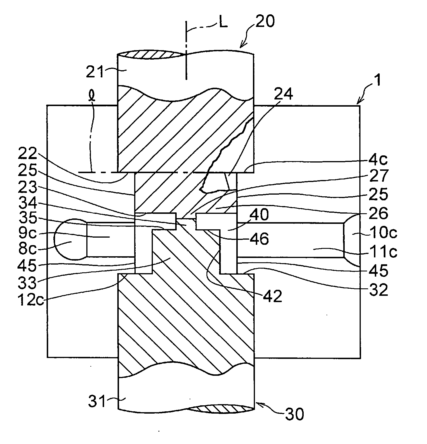
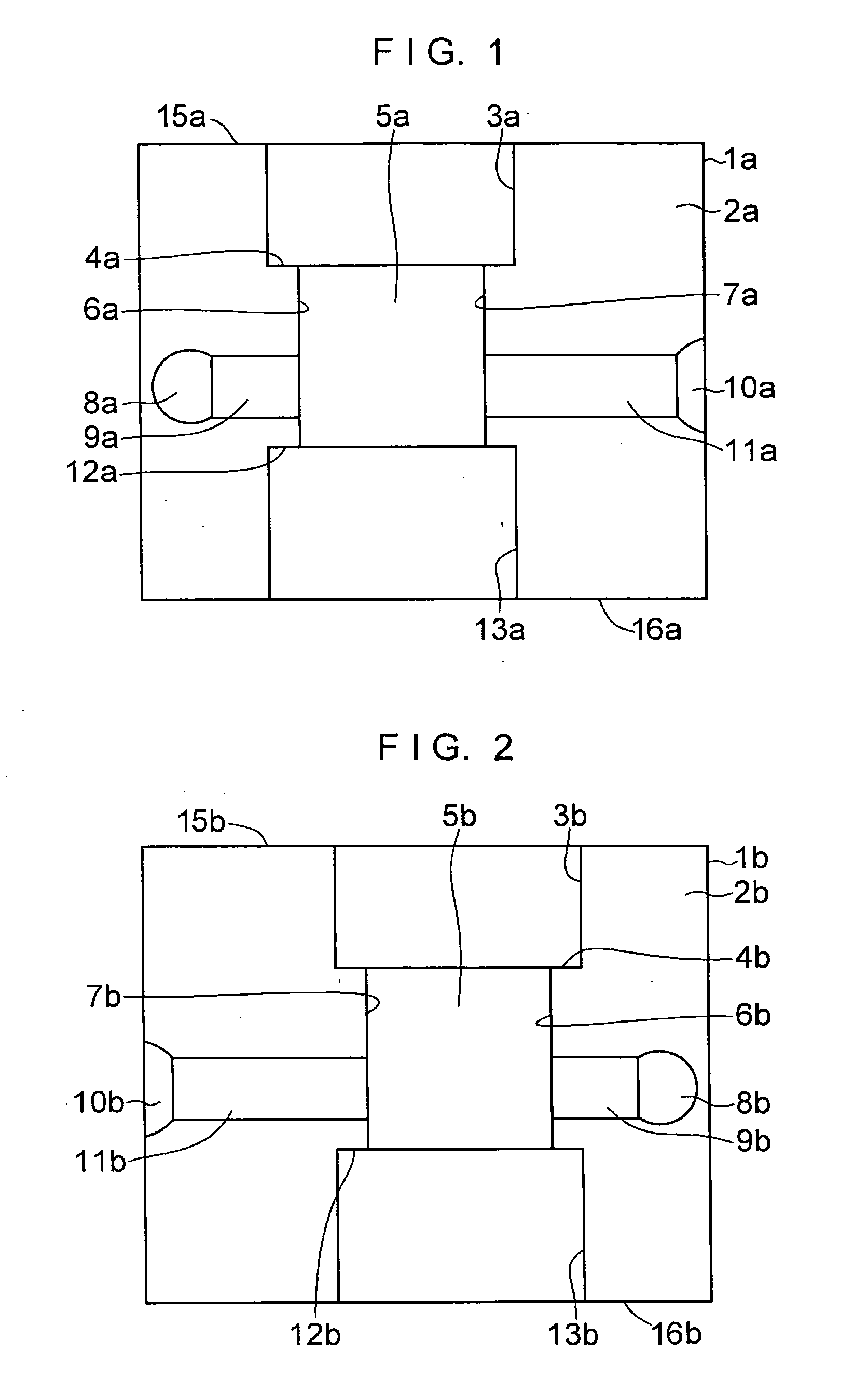
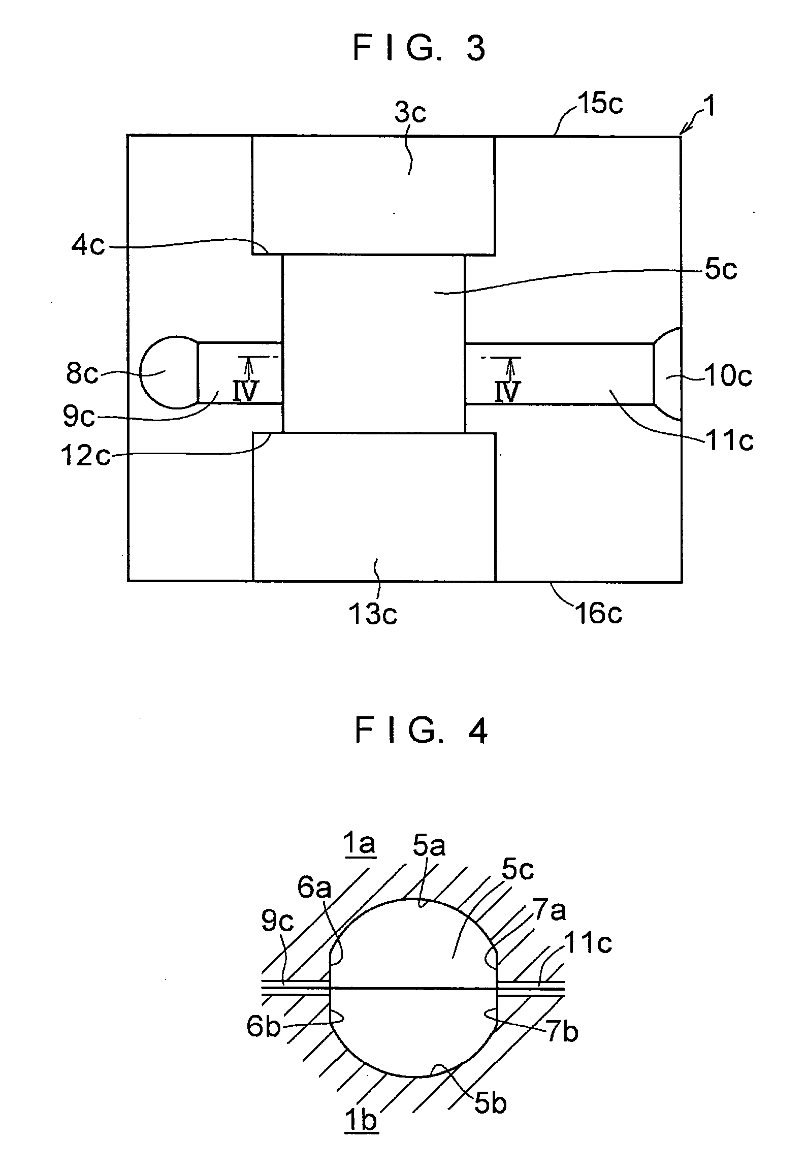
[0059] In FIGS. 1 to 6, a die 1 is formed by a lower die half 1a and an upper die half 1b which are split in two. As shown in FIG. 1, the lower die half 1a is comprised of a semicylindrical concave surface 3a for forming a semicylindrical concave portion which is formed in one surface 2a and is open in one end face 15a of the upper die half 1a; a semicylindrical concave surface 5a whose diameter is reduced relative to that semicylindrical concave surface 3a via an annular stepped portion 4a and which forms a semicylindrical concave portion of an intermediate portion; planar surfaces 6a and 7a formed in face-to-face relation to each other at both edges of that semicylindrical concave surface 5a; a recessed channel 9a with a rectangular cross section having one end communicating with the planar surface 6a and the other end communicating with a recess 8a constituting an overflow well; a recessed channel 11a with a rectangular cross section having one end communicating with the planar s...


PUM

PropertyMeasurementUnit
Diameteraaaaaaaaaa
Widthaaaaaaaaaa

Abstract

A rack guide includes a rack guide base body which has on its outer peripheral surface a pair of semicylindrical surfaces and a pair of planar surfaces each located between the pair of semicylindrical surfaces, has a concavely recessed surface located on one axial end portion side inwardly of the pair of semicylindrical surfaces and the planar surfaces, and has a cylindrical surface located on the other axial end portion side inwardly of the pair of semicylindrical surfaces and the planar surfaces; and a slider secured to the rack guide base body.

Description

TECHNICAL FIELD [0001] The present invention relates to a rack-and-pinion type steering apparatus. BACKGROUND ART [0002] A rack-and-pinion type steering apparatus is generally comprised of a housing, a pinion rotatably supported by this housing, a rack bar on which rack teeth meshing with this pinion are formed, a rack guide disposed in a housing to slidably support the rack bar, and a spring for pressing this rack guide toward the rack bar. [0003] In such a rack-and-pinion type steering apparatus, an iron-based sintered metal or a synthetic resin is used for the rack guide for slidably supporting the rack bar. However, in the case of the rack guide formed of an iron-based sintered metal, although it has sufficient mechanical strength against an impact load from the rack bar, the efficiency of a steering system declines since the frictional resistance to sliding is large, so that a problem remains in controllability. Meanwhile, as for the rack guide formed of a simple substance of s...

Claims


Application Information

Patent Timeline
IPC IPC(8): B60K17/34B22D17/00B22D17/22B62D3/12F16H55/28
CPCB22D17/00B22D17/22Y10T74/1967F16H55/283B62D3/123
Inventor YAMAMOTO, KAZUHIROHIROSE, MASAHIKONISHIMURA, KATSUTOSHISHIMURA, MASAOKUZUMI, YOSHIRO
Owner JTEKT CORP
Why Eureka
Eureka Blog
Learn More