Image display apparatus

a technology of image display and display screen, which is applied in the field of image display apparatus, can solve the problems of affecting the display effect, and damaging the electron source, and achieves the effects of reducing the influence of a magnetic field, small luminance unevenness, and small luminance change with tim

Inactive Publication Date: 2006-03-02
CANON KK +1
View PDF18 Cites 13 Cited by
  • Summary
  • Abstract
  • Description
  • Claims
  • Application Information

AI Technical Summary

Benefits of technology

[0008] The present invention has been made with a view to solving the above problems, and therefore an object of the present invention is to provide: an image display apparatus which reduces an influence of a magnetic field when an

Problems solved by technology

When a gas is generated in the vacuum container to increase the pressure in the container, the increase adversely affects the electron sources to reduce an electron emission amount, thereby making it impossible to display a clear image, although the degree of the adverse effect varies depending on the kind of the gas.
I

Method used


Image

  • Image display apparatus
  • Image display apparatus
  • Image display apparatus

Examples


embodiment 1

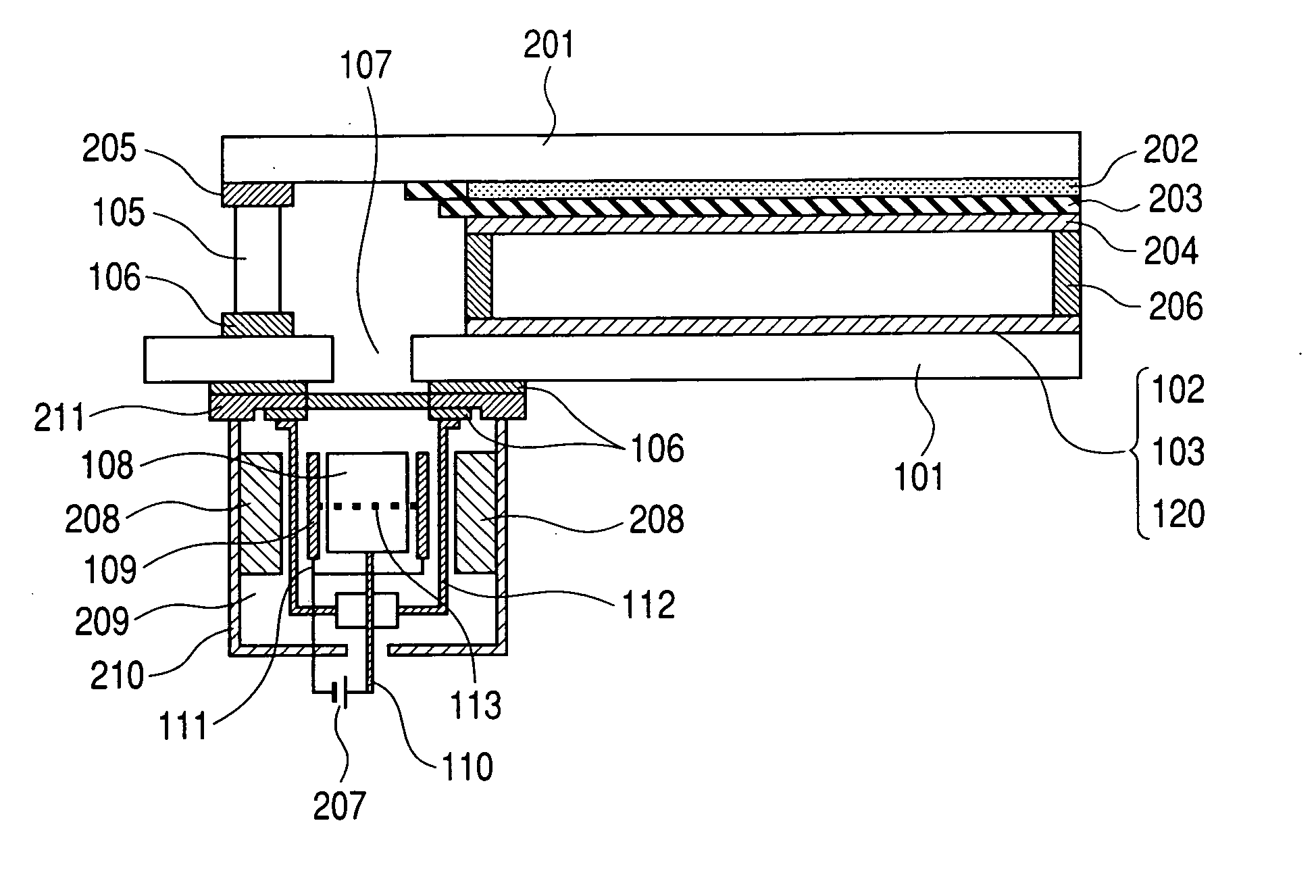
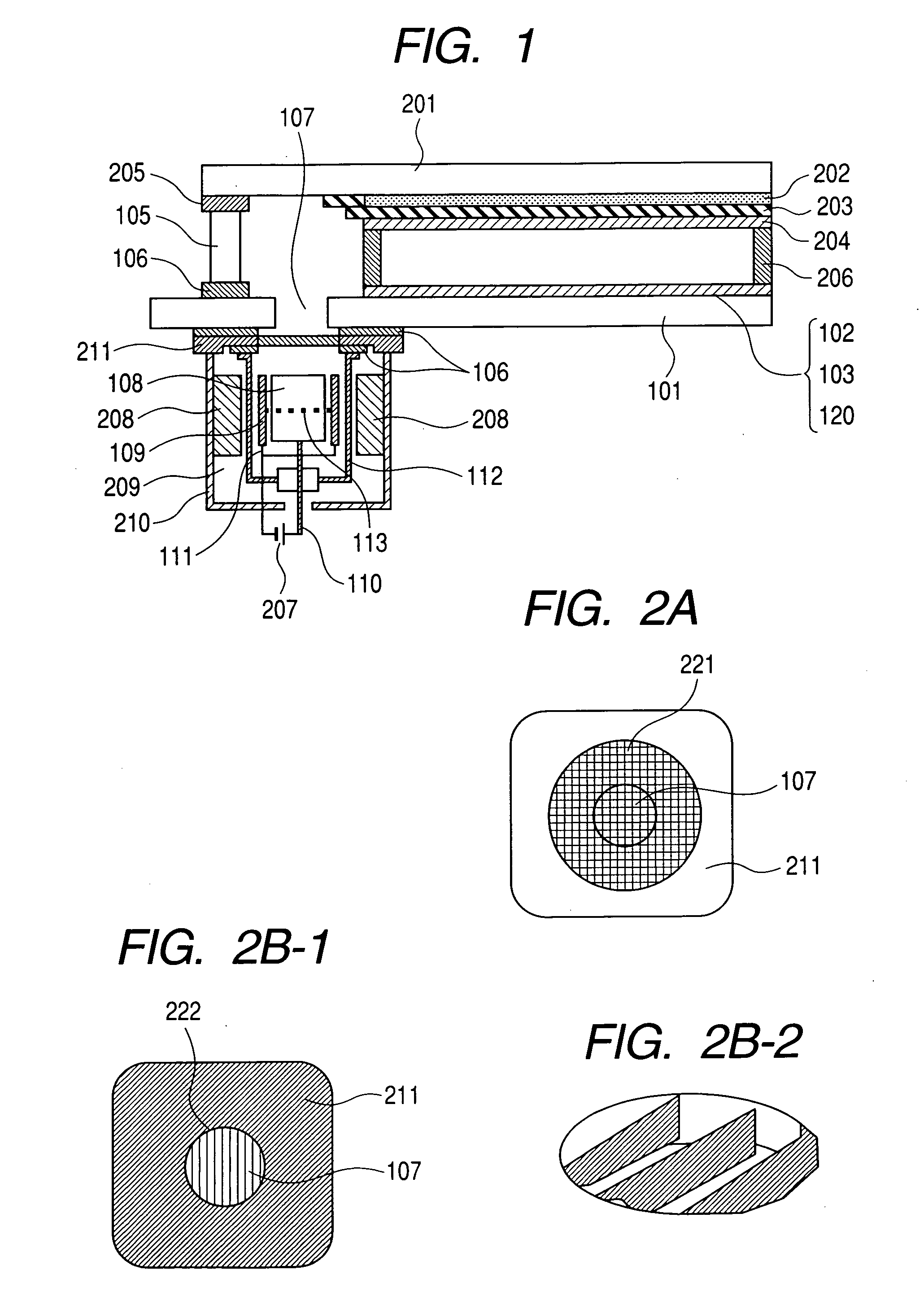
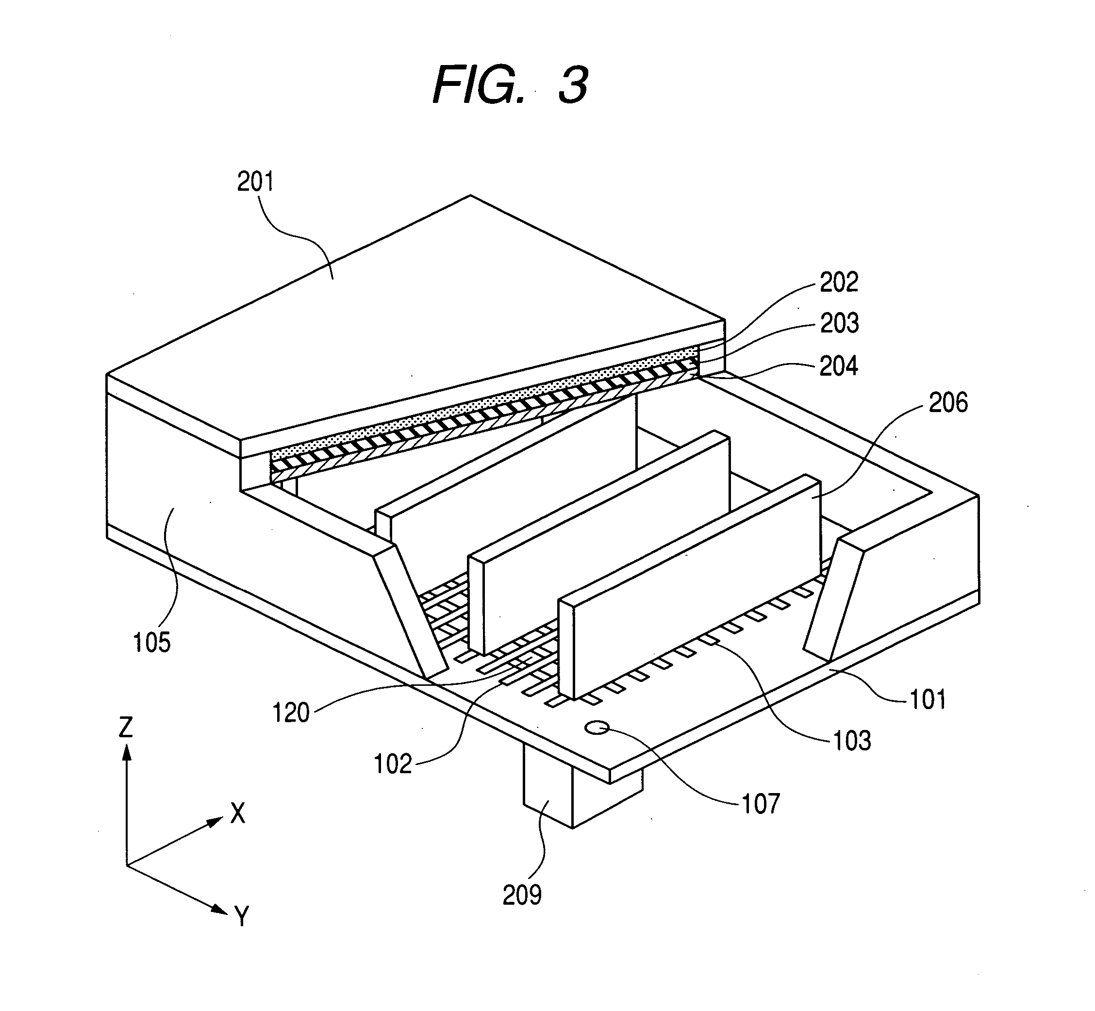
[0088] The structure of an image display apparatus attached with an ion pump with a magnetic shielding member arranged between an electron-emitting device and the ion pump will be described with reference to FIG. 1 and FIGS. 2A, 2B-1, and 2B-2, and a method of producing a vacuum container serving as the image display apparatus will be described with reference to FIGS. 3 to 7.

[0089] First, a method of producing a hermetic container as an image display apparatus will be described. Soda glass having a thickness of 2.8 mm and a size of 240 mm×320 mm (SL: manufactured by Nippon Sheet Glass Co., Ltd.) was used as the rear plate 101, and soda glass having a thickness of 2.8 mm and a size of 190 mm×270 mm (SL: manufactured by Nippon Sheet Glass Co., Ltd.) was used as the face plate 201. The exhaust port 107 of 8 mmΦ was opened in the rear plate 101 at a position outside an image area and inside the glass frame 105.

[0090] The device electrodes 402 and 403 of the surface conduction electron...

embodiment 2

[0115] As shown in FIGS. 2B-1 and 2B-2, a base plate of a magnetic shield case was produced by: perforating a permalloy plate having a thickness of 1.5 mm with holes; and attaching, to the hole portions, 4 stripe shaped permalloy plates each having a thickness of 0.3 mm and a width of 3 mm by means of spot-welding in such a manner that a width direction would be perpendicular to the surface of the base plate. Each stripe shaped plate had such length that would be stored in the communicating path 107 arranged in the rear plate. Then, an image display apparatus and an ion pump were produced in the same manner as in Embodiment 1 except that the portions of the stripe shaped plates were placed into the communicating path arranged in the rear plate and the base plate was bonded by means of frit glass.

[0116] The luminance distribution of the image display apparatus produced in Embodiment 2 was measured. As a result, a reduction in luminance was suppressed to 4% or less even in the vicini...

embodiment 3

[0117] In each of Embodiments 1 and 2, a glass member having a coefficient of thermal expansion close to that of frit glass was used for the ion pump casing 112 because the ion pump casing was connected to the rear plate 101 by means of the frit glass 106. In the case where glass is used, there is no need to electrically insulate the anode connection terminal 110, but the terminal must be vacuum-sealed with frit glass or the like.

[0118] In Embodiment 3, a stainless case was used for the ion pump casing 112. In this case, electrical glass made of alumina was used for electrically insulating the anode connection terminal 110.

[0119] Bonding of the base plate 211 of the permalloy magnetic shield case with the rear plate 101, and bonding of the ion pump casing 112 with the base plate 211 were each performed by means of an epoxy-based adhesive. The rear plate and the face plate were subjected to seal bonding in a vacuum at 100° C. An image display apparatus and an ion pump were produced...


PUM


Abstract

In an image display apparatus composed of a vacuum container having an electron source composed of multiple electron-emitting devices and a phosphor film that is irradiated with an electron from the electron source to emit light for display, an ion pump for exhausting the vacuum container through a communicating path by virtue of an action of a magnetism forming portion is arranged. A magnetic shielding member is arranged in a space where the ion pump and the electron-emitting devices are in communication with each other, whereby an influence of a magnetic field generated by the magnetism forming portion on the trajectory of an electron emitted from any one of the electron-emitting devices and display luminance unevenness incidental to the influence are removed.

Description

BACKGROUND OF THE INVENTION [0001] 1. Field of the Invention [0002] The present invention relates to an image display apparatus using an electron-emitting device. [0003] 2. Background Art [0004] In a flat display in which: a large number of electron-emitting devices are arranged as electron sources on a flat substrate; a phosphor as an image forming member on an opposing substrate is irradiated with electron beams emitted from the electron sources; and the phosphor is allowed to emit light to display an image, the inside of a vacuum container including the electron sources and the image forming member must be kept at a high vacuum. When a gas is generated in the vacuum container to increase the pressure in the container, the increase adversely affects the electron sources to reduce an electron emission amount, thereby making it impossible to display a clear image, although the degree of the adverse effect varies depending on the kind of the gas. [0005] In particular, the following p...

Claims


Application Information

Patent Timeline
IPC IPC(8): H01J31/00H01J31/26H01J31/12
CPCH01J29/867H01J2329/943H01J2329/868H01J31/123H01J31/12
Inventor TSUDA, HISANORIKAMIO, MASARUGOFUKU, IHACHIROSATO, YASUESHIMADA, YOSHIYUKIMITANI, HIROMASASEINO, KAZUYUKINISHIMURA, TAKASHI
Owner CANON KK
Why Eureka
Try Eureka