Physical quantity sensor with trimming function
- Summary
- Abstract
- Description
- Claims
- Application Information
AI Technical Summary
Benefits of technology
Problems solved by technology
Method used
Image

Examples
first embodiment
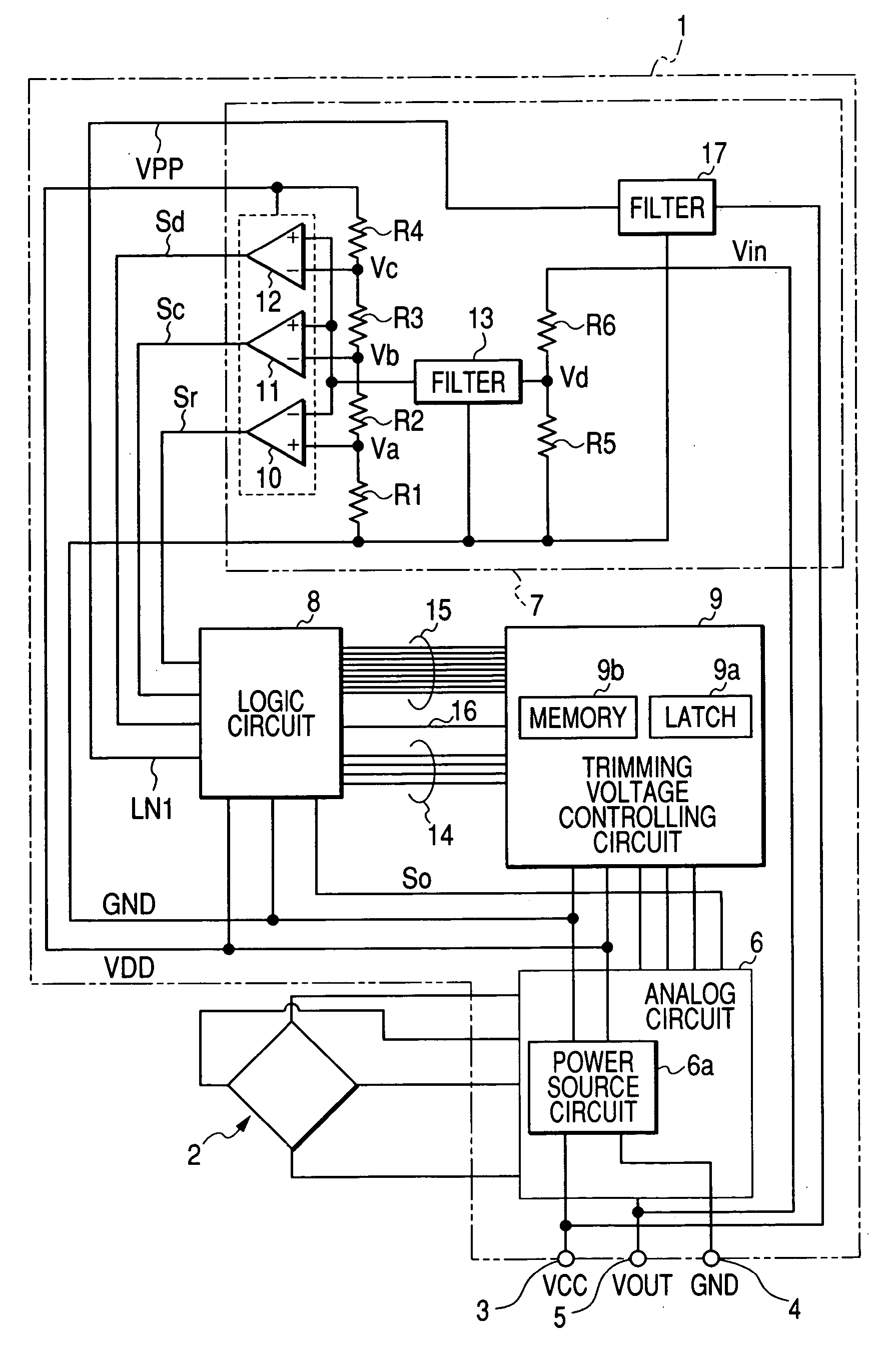
[0035] Hereinafter, a first embodiment of the present invention will be explained with reference to FIGS. 1 to 6. FIG. 1 shows an electric arrangement of a CMOS sensor circuit 1 incorporating a trimming circuit together with a sensing element 2. This sensor circuit 1 forms a unit for driving the sensing element 2, which is one aspect of the present invention.
[0036] Thus the sensor circuit 1 (i.e., sensing element driving unit) and the sensing element 2 forms the sensor for sensing a physical quantity.
[0037] The sensor circuit 1 is connected to a sensing element 2 which, for example, acts as a physical quantity sensor. The sensing element 2 consists of four piezoelectric elements connected in a predetermined bridge pattern. The sensor circuit 1 has an output terminal 5 which produces a sensor output having a voltage corresponding to an output signal of the sensing element 2 (corresponding to a detection signal) in an ordinary operation state.
[0038] Furthermore, the sensor circuit ...
second embodiment
[0075] Next, a second embodiment of the present invention will be explained with reference to FIG. 7. FIG. 7 shows an electric arrangement of a CMOS sensor incorporating a trimming circuit. The portions and components identical with those shown in FIG. 1 are denoted by the same reference numerals. A sensor circuit 29 of the second embodiment is arranged to give both the trimming data and the write voltage VPP of the memory 9b from the output terminal 5 in the trimming operation state. The rest of the trimming procedure is substantially identical with that of the sensor circuit 1 explained in the first embodiment.
[0076] In a control signal separation circuit 30 (corresponding to the data separation circuit), the output terminal 5 is connected via the filter 17 to the serial circuit of resistors R5 and R6. Furthermore, a joint of the filter 17 aid the resistor R6 is connected via a switching circuit 31 (corresponding to a write voltage switching circuit) to the output line of the pow...
third embodiment
[0081] Next, a third embodiment of the present invention will be explained with reference to FIGS. 8 and 9. FIG. 8 shows an electric arrangement of a CMOS sensor incorporating a trimming circuit. The portions and components identical with those shown in FIG. 1 are denoted by the same reference numerals. A sensor circuit 32 of the third embodiment is arranged to give both the trimming data and the write voltage VPP from the output terminal 5 in the trimming operation state, like the sensor circuit 29 explained in the second embodiment. The sensor circuit 32 of the third embodiment, in order to prevent inversion of the substrate potential of the above-described logic circuit 8, includes a switching circuit 33 (corresponding to the write voltage switching circuit) that selects a higher voltage between the constant voltage VDD supplied from the power source circuit 6a and the voltage of output terminal 5 having passed the filter 17 and outputs the selected voltage to the write voltage s...
PUM
 Abstract
Description
Claims
Application Information
 - R&D
- Intellectual Property
- Life Sciences
- Materials
- Tech Scout
- Unparalleled Data Quality
- Higher Quality Content
- 60% Fewer Hallucinations
Browse by: Latest US Patents, China's latest patents, Technical Efficacy Thesaurus, Application Domain, Technology Topic, Popular Technical Reports.
© 2025 PatSnap. All rights reserved.Legal|Privacy policy|Modern Slavery Act Transparency Statement|Sitemap|About US| Contact US: help@patsnap.com