Reconfigurable power transistor using latching micromagnetic switches

Inactive Publication Date: 2006-03-02
SCHNEIDER ELECTRIC IND SAS
View PDF43 Cites 10 Cited by
  • Summary
  • Abstract
  • Description
  • Claims
  • Application Information

AI Technical Summary

Benefits of technology

[0011] The latching micromagnetic switch of the present invention can be used in a plethora of products including household and industrial appliances, consumer electronics, military hardware, medical devices and vehicles of

Problems solved by technology

Such relays typically exhibit a number of marked disadvantages, however, in that they generally exhibit only a single stable output (i.e., the quiescent state) and they are not latching (i.e., they do not retain a constant output as power is removed from the relay).
Moreover, the spring required by conventional micromagnetic relays may degrade or brea

Method used


Image

  • Reconfigurable power transistor using latching micromagnetic switches
  • Reconfigurable power transistor using latching micromagnetic switches
  • Reconfigurable power transistor using latching micromagnetic switches

Examples


Embodiment Construction

Introduction

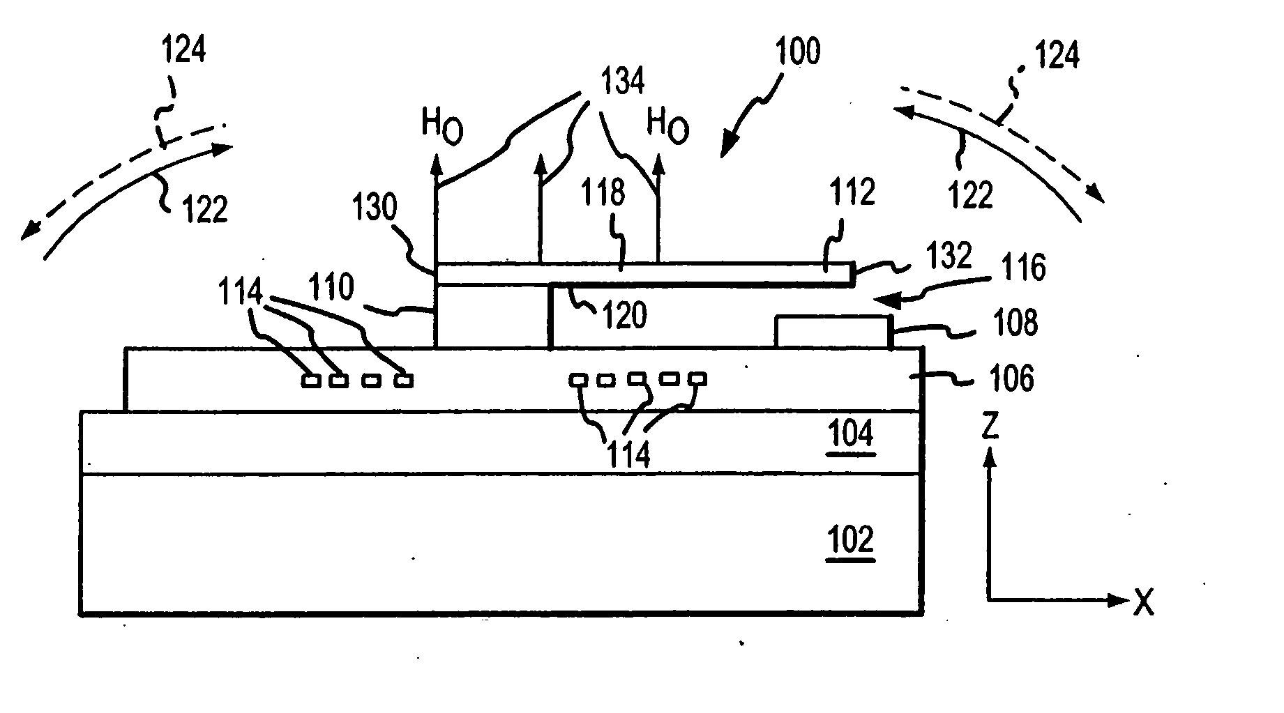
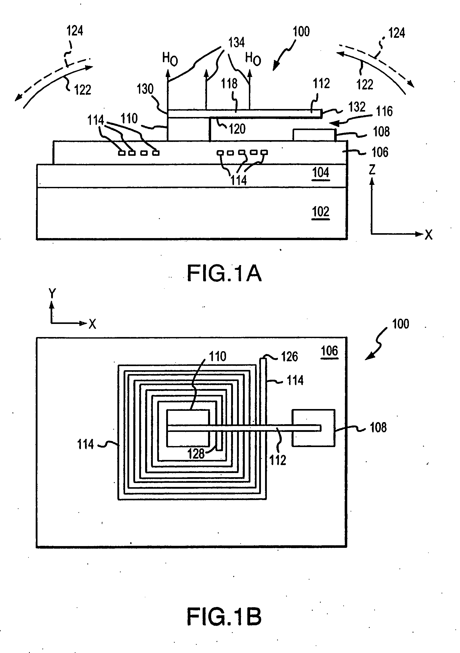
[0029] It should be appreciated that the particular implementations shown and described herein are examples of the invention and are not intended to otherwise limit the scope of the present invention in any way. Indeed, for the sake of brevity, conventional electronics, manufacturing, MEMS technologies and other functional aspects of the systems (and components of the individual operating components of the systems) may not be described in detail herein. Furthermore, for purposes of brevity, the invention is frequently described herein as pertaining to a micro-electronically-machined relay for use in electrical or electronic systems. It should be appreciated that many other manufacturing techniques could be used to create the relays described herein, and that the techniques described herein could be used in mechanical relays, optical relays or any other switching device. Further, the techniques would be suitable for application in electrical systems, optical systems, co...


PUM


Abstract

An apparatus includes an circuit and a latching micromagnetic switch that controls energy flow through the circuit. The latching micromagnetic switch includes a cantilever, a permanent magnet, and a coil configured to latch the latching micromagnetic switch in one of two positions each time energy passes through the coil. The electrical device and the latching micromagnetic switch can be integrated on a same substrate. Otherwise, the electrical device and the latching micromagnetic switch can be located on separate substrates and coupled together. The circuit can be a transistor or an array of transistors connected in parallel. If the circuit is an array of transistors, there can be an array of the switches, where each one of the switches is coupled to a corresponding one of the transistors. The switches are coupled to at least one of a source, drain, or gate of the corresponding transistor.

Description

RELATED APPLICATIONS [0001] This application is a continuation of U.S. Ser. No. 10 / 156,764, filed May 9, 2002, which claims priority under 35 U.S.C. §119(e) to U.S. Provisional Patent Application No. 60 / 293,515, filed May 29, 2001, which are both incorporated by reference herein in their entireties. [0002] The application is related to (2040.0010002) U.S. application Ser. No. 10 / 147,918, filed May 20, 2002, and entitled “Apparatus Utilizing Latching Micromagnetic Switches,” which is incorporated by reference herein in its entirety.BACKGROUND OF THE INVENTION [0003] 1. Field of the Invention [0004] The present invention relates to an electrical apparatus having an electronic device with its energy flow controlled by switches. [0005] 2. Background Art [0006] Switches are typically electrically controlled two-state devices that open and close contacts to effect operation of devices in an electrical or optical circuit. Relays, for example, typically function as switches that activate or...

Claims


Application Information

Patent Timeline
IPC IPC(8): H01H51/22H01H50/00
CPCH01H2050/007H01H50/005
Inventor VAITKUS, RIMANTASWHEELER, CHARLESSHEN, JUNRUAN, MEICHUN
Owner SCHNEIDER ELECTRIC IND SAS
Why Eureka
Try Eureka