
Apparatus for image processing

an image processing and apparatus technology, applied in the field of apparatus for image processing, can solve the problem of not having an apparatus that integrates these techniques together to provide high performance, and achieve the effect of high performan

Inactive Publication Date: 2006-03-02
KK TOSHIBA +1
View PDF16 Cites 67 Cited by
  • Summary
  • Abstract
  • Description
  • Claims
  • Application Information

AI Technical Summary

Benefits of technology

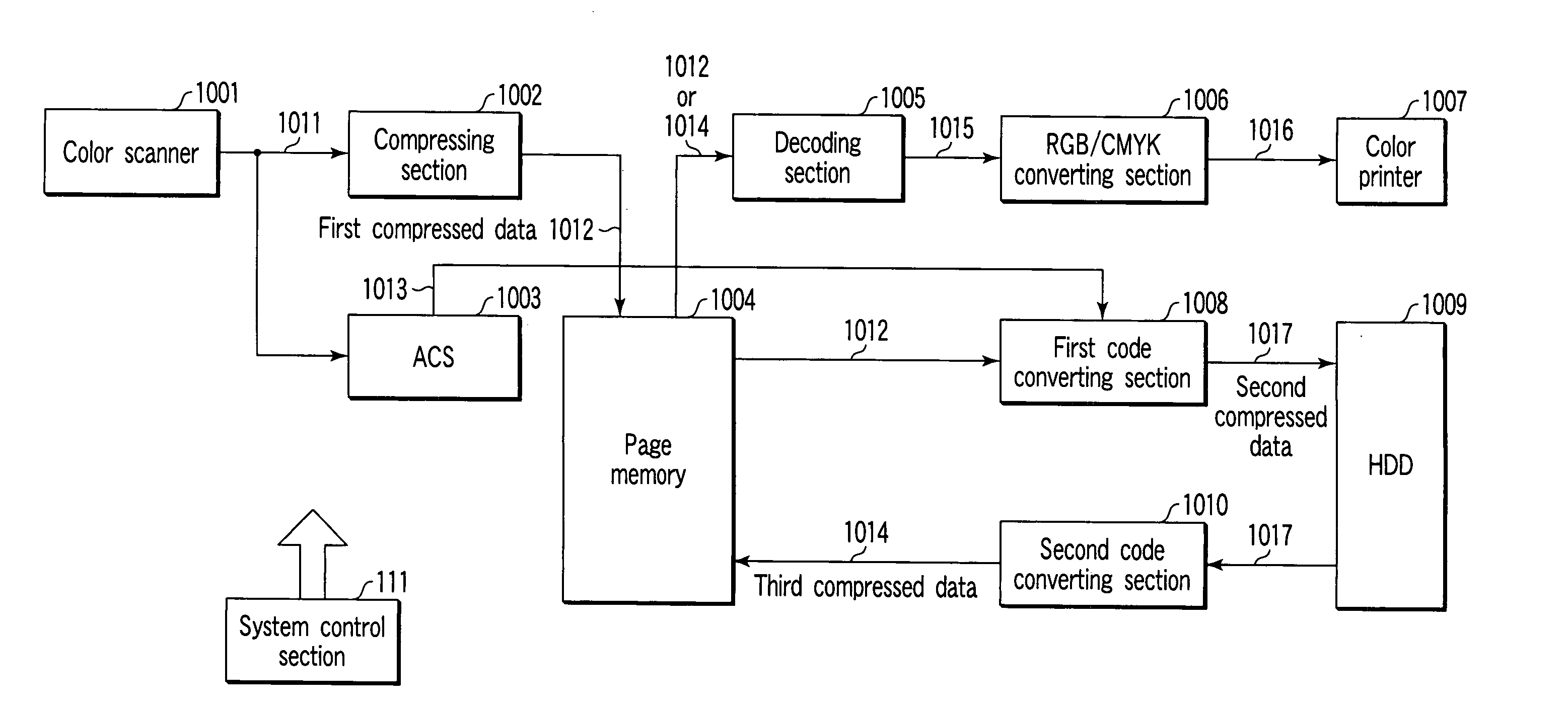
[0023] As described above, for copying apparatuses, plural types of compressing and decoding techniques, data storing techniques, data determining techniques, and the like have been developed. However, there are no apparatuses that integrate these techniques together to provide high performance.
[0024] It is thus an object of the present invention to provide an apparatus for image processing which effectively utilizes diverse compressing and decoding systems, that is, selectively applies a plurality of compressing systems or combines them with each other to improve accumulation efficiency while allowing image data to be properly edited.

Problems solved by technology

However, there are no apparatuses that integrate these techniques together to provide high performance.

Method used


Image

  • Apparatus for image processing
  • Apparatus for image processing
  • Apparatus for image processing

Examples


first embodiment

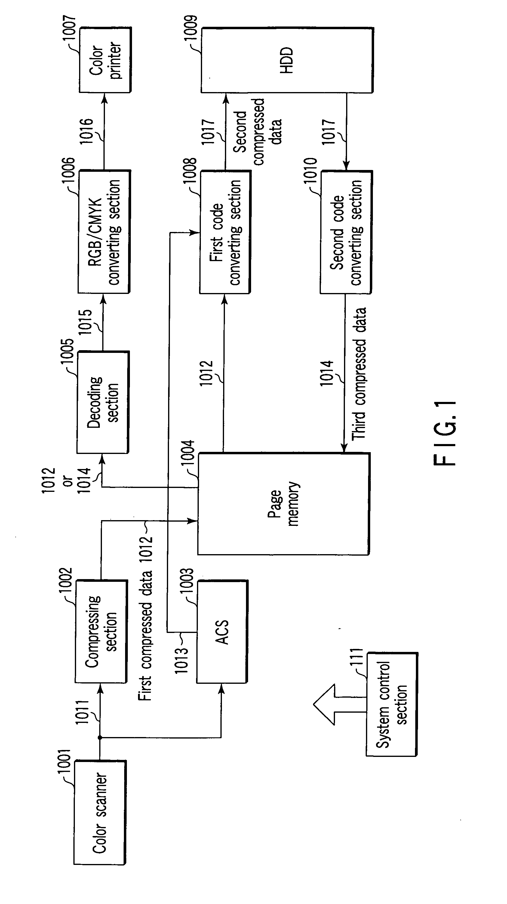
[0125]FIG. 12 shows a first variation of the A color printer controller 1001e1 provides an image signal 1010e1. This image signal is for C, M, Y, and K. A plane determining section 1003e1 is used to determine whether the image is colored or monochromatic. A compressing section 1002e1, a page memory 1004e1, a decoding section 1005e1, a color printer 1006e1, a first code converting section 1007e1, a hard disk device 1008e1, and a second code converting section 1009e1 are the same as the compressing section 1002, page memory 1004, decoding section 1005, color printer 1006, first code converting section 1007, hard disk device 1008, and second code converting section 1009, shown in FIG. 1.

[0126]FIG. 13 shows an example of the configuration of the plane determining section 1003e1. Input image signals include C (a cyan signal), M (a magenta signal), Y (a yellow signal), and K (a black signal). The signals 1010e1-C, 1010e1-M, 1010e1-Y, and 1010e1-K are inputted to the corresponding raster / ...

embodiment 1

[0138] The third code converting section 1018e2 removes the color determination, the identification code, and the marker code. Then, if the entire ACS determination result is “1” (color), then for each block for which the block color determination result is “0”, the third code converting section 1018e2 adds the code information CbCr=0 to the output 1017e2 similarly to the decoding section 1005 in The third code converting section 1018e2 thus considers the output 1017e2 to be a colored file. The third code converting section 1018e2 then adds JPEG header information to the output 1017e2 to the convert it into the fourth compressed data 1019e2. This corresponds to a point (P20), a characteristic point of the present apparatus, described later.

[0139] If the entire ACS determination result is“0”, indicating a monochromatic image, the first code converting section 1008e2 removes all of the Cb and Cr information, leaving only the Y code. Consequently, the third code converting section 101...


PUM


Abstract

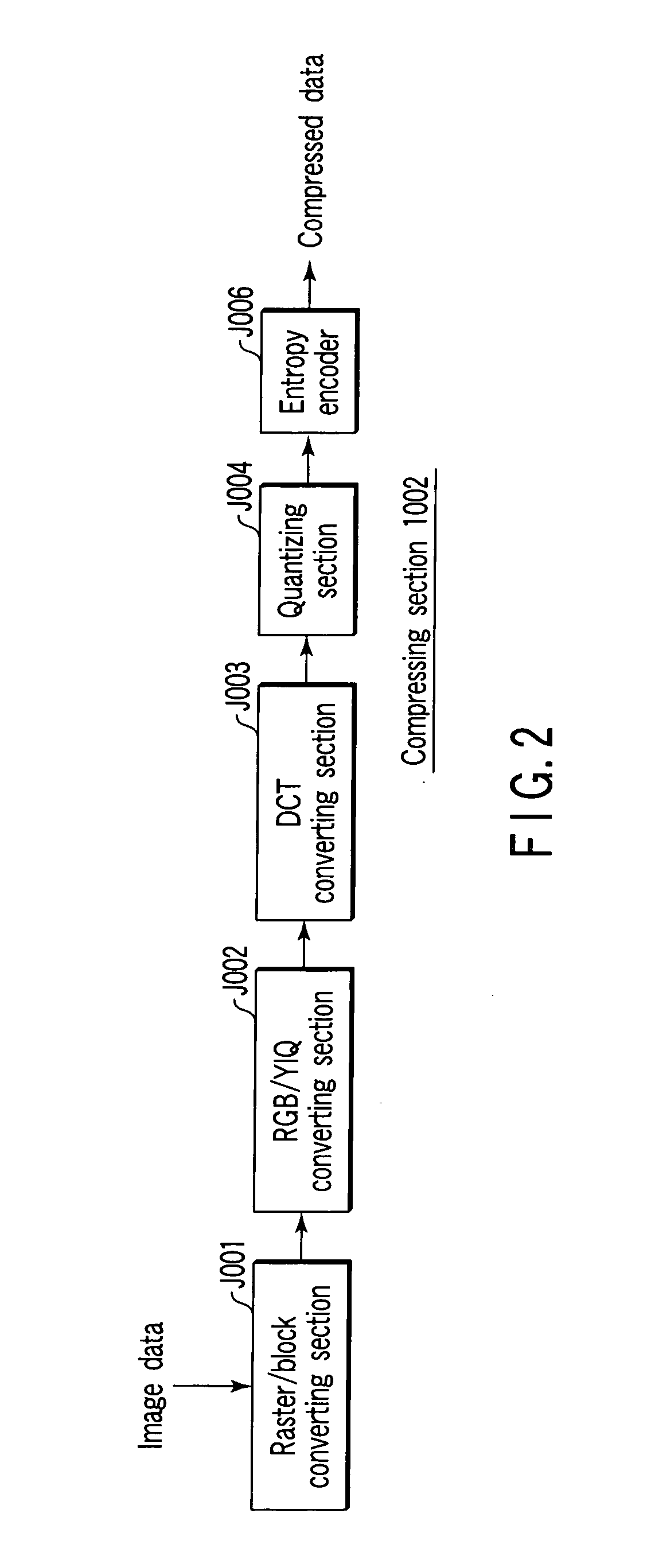
An image processing apparatus according to an embodiment of the present invention has a first compressing section which compresses each block of an image into first compressed data, a first code converting section which converts the first compressed data into second compressed data, a second code converting section which converts the second compressed data into third compressed data, and a decoding section which decodes the third compressed data. In this case, each block of the second compressed data has a code length equal to or different from that of each block of the first compressed data. Each block of the third compressed data has a code length equal to that of each block of the first compressed data.

Description

BACKGROUND OF THE INVENTION [0001] 1. Field of the Invention [0002] The present invention relates to an apparatus for image processing which is effectively used in, for example, a digital copier. [0003] 2. Description of the Related Art [0004] Some digital copiers have a single copying function with which a user manually places documents to be copied, in a scan section of the copier one by one and then copies the documents, and a continuous copying function to automatically sort large quantities of documents and then continuously copy them to a large number of sheets or continuously copy even only one document to a large number of sheets. Other digital copiers are equipped with an editing function to carry out editions (image synthesis, image reduction, and the like) utilizing temporarily saved data. [0005] When the single copying function, the continuous copying function, or the editing function is executed, it is necessary to effectively utilize an image compressing process, a dec...

Claims


Application Information

Patent Timeline
Patent Type & Authority Applications(United States)
IPC IPC(8): G06F15/00G06T9/00H04N1/40H04N1/41H04N1/413H04N1/46H04N19/00
CPCH04N1/642H04N19/40H04N21/4302H04N21/242
Inventor TABATA, SUNAOKANNO, HIROKI
Owner KK TOSHIBA
Learn More