
CPP spin valve with ultra-thin CoFe(50%) laminations

Inactive Publication Date: 2006-03-02
HEADWAY TECH INC
View PDF7 Cites 4 Cited by
  • Summary
  • Abstract
  • Description
  • Claims
  • Application Information

AI Technical Summary

Benefits of technology

[0015] It has been an object of at least one embodiment of the present inve

Problems solved by technology

However, it has also been found that using CoFe(50%) for AP1 resulted in poor EM (electro-migration) and larger device to device variation.

Method used


Image

  • CPP spin valve with ultra-thin CoFe(50%) laminations
  • CPP spin valve with ultra-thin CoFe(50%) laminations

Examples


Embodiment Construction

[0023] It is known that in CPP spin valve structures interface scattering, as well as bulk scattering, contributes to GMR. The present invention makes use of this by depositing an ultra-thin layer on top of the conventional under-layer so as to influence subsequent film growth. This increases the CPP GMR ratio while maintaining the basic CoFe(25%) growth structure.

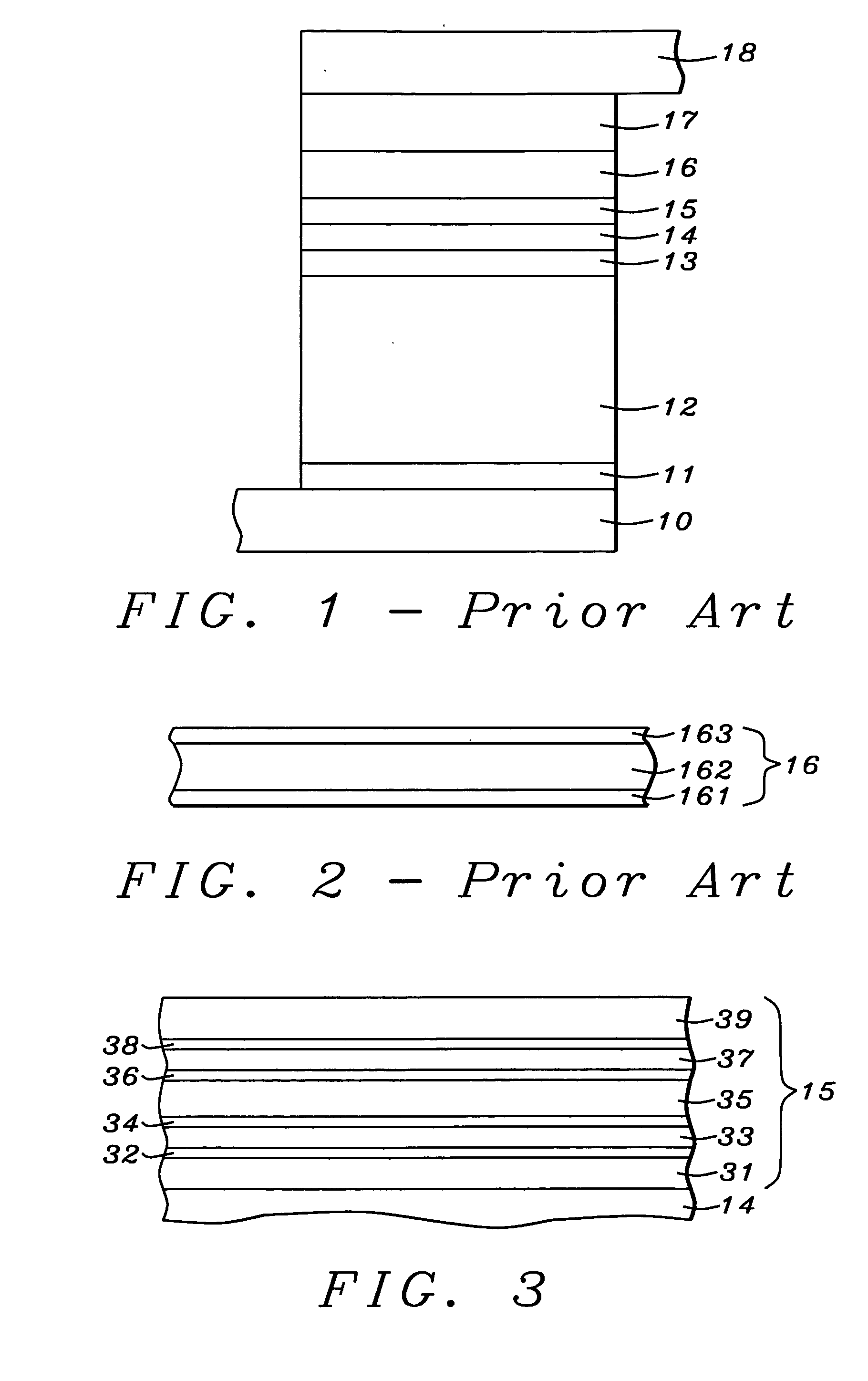
[0024] We now disclose the present invention through a description of a process for its manufacture. Referring initially to FIG. 1, the process begins with the provision of substrate 10 and depositing thereon seed layer 11. A pinning (AFM) layer 12 of IrMn is laid down on seed layer 11 to a thickness between 30 and 70 Angstroms, followed by AP2 layer 13. Then, AFM coupling layer 14 is deposited onto AP2 layer 13. The latter is a material such as CoFe (more specifically FeCO3) and is deposited to a thickness between about 20 and 60 Angstroms.

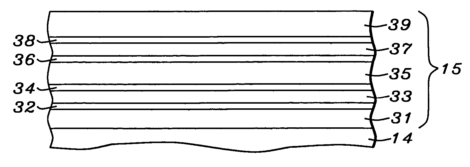
[0025] At this point in the process the key novel feature of the invention (the f...


PUM


Abstract

Fe rich CoFe can be used in AP1 to enhance CPP GMR. However, this is found to degrade the electro-migration performance of the device. This problem has been solved by using an AP1 that is a laminate of several CoFe(25%) layers, separated from one another by copper layers. Ultra-thin layers of iron-rich CoFe are then inserted at all the copper-CoFe interfaces.

Description

FIELD OF THE INVENTION [0001] The invention relates to the general field of CPP GMR read heads with particular reference to the AP1 portion of the pinned layer. BACKGROUND OF THE INVENTION [0002] The principle governing the operation of most magnetic read heads is the change of resistivity of certain materials in the presence of a magnetic field (magneto-resistance or MR). Magneto-resistance can be significantly increased by means of a structure known as a spin valve where the resistance increase (known as Giant Magneto-Resistance or GMR) derives from the fact that electrons in a magnetized solid are subject to significantly less scattering by the lattice when their own magnetization vectors (due to spin) are parallel (as opposed to anti-parallel) to the direction of magnetization of their environment. [0003] The key elements of a spin valve are illustrated in FIG. 1. They are a substrate 10, which could be a lower magnetic shield and / or a lower lead, on which is seed layer 11. Anti...

Claims


Application Information

Patent Timeline
IPC IPC(8): G11B5/33G11B5/127
CPCB82Y10/00G11B2005/3996G11B5/3929B82Y25/00
Inventor LI, MINZHANG, KUNLIANGHORNG, CHENG T.TORNG, CHYU JIUHCHEN, YU-HSIATONG, RU-YING
Owner HEADWAY TECH INC
Learn More