
Vehicular power converter

a power converter and case technology, applied in the direction of cooling/ventilation/heating modification, semiconductor/solid-state device details, semiconductor devices, etc., can solve the problems of increased costs, limited reliability, and inability to provide ventilating holes in the case for the above-mentioned vehicle-mounted application, and achieve high reliability and effectively radiate heat generated

Inactive Publication Date: 2006-03-02
MITSUBISHI ELECTRIC CORP
View PDF2 Cites 80 Cited by
  • Summary
  • Abstract
  • Description
  • Claims
  • Application Information

AI Technical Summary

Benefits of technology

[0011] The present invention has been made to solve the problem described above, and an object of the present invention is to provide a vehicular power converter with high reliability by effectively radiating heat generated in a power circuit section and control circuit section without using a cooling fan.
[0013] The vehicular power converter according to the present invention, since it is configured as described above, each heat radiation path of the power circuit section and the control circuit section can be maintained; and since each heat exchange section of the power circuit section and the control circuit section are disposed in a space on one main surface part and the other main surface part of the outer circumferential part of the housing, the cooling air flow is divided, and therefore, heat-exchanged air flows at respective heat exchange sections do not interfere with each other. Consequently, a cooling structure with superior efficiency can be provided without providing a ventilating hole, a cooling fan, and the like; therefore, it is particularly effective for use in a vehicle-mounted power converter which is used in harsh environments.

Problems solved by technology

In the above-mentioned known technology, some cost for mounting cooling fans on the case and consideration for the life-time of the fan are required and, more particularly, when this technology is applied to a power converter for use in a much more harsh environment, for example, in the case of a vehicular power converter, the reliability has been limited.
Further, there has been a problem in that provision of ventilating holes in the case cannot be applied for the above-mentioned vehicle-mounted application and apparatus for use in such an environment necessary for waterproof protection.
Therefore, there is a problem in that cooling means for cooling the control circuit section is required to provide a heat radiation performance that can handle a heat generation which is larger than the heat generation of the control circuit section, resulting in increased costs.

Method used


Image

  • Vehicular power converter
  • Vehicular power converter
  • Vehicular power converter

Examples


embodiment 1

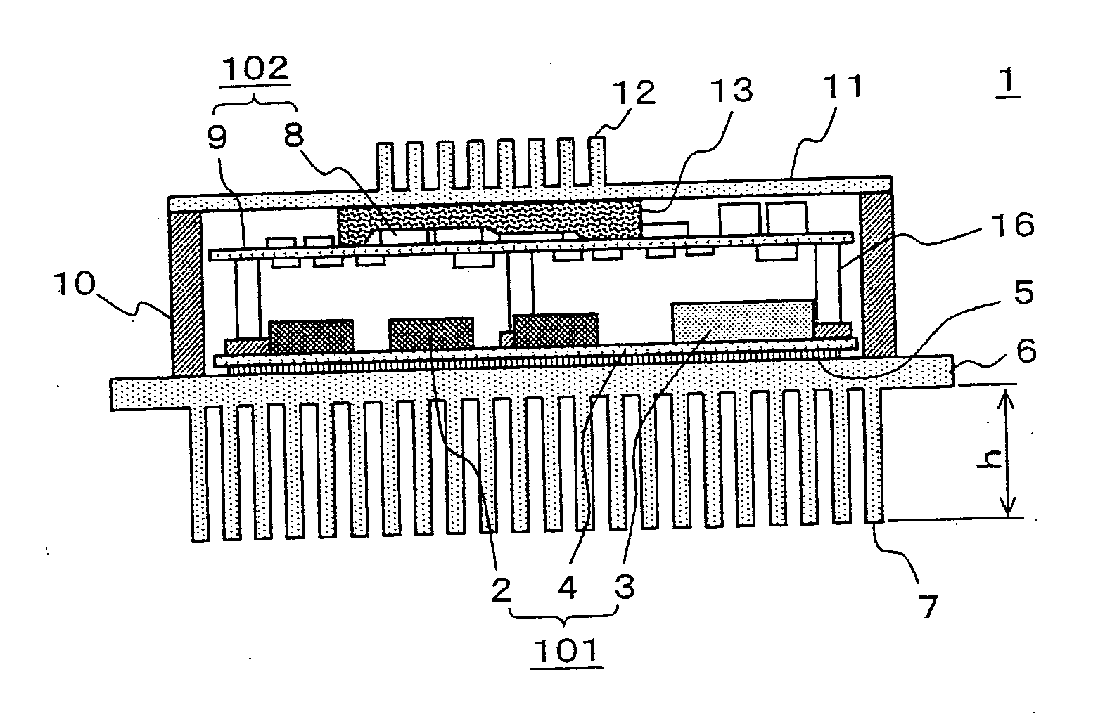
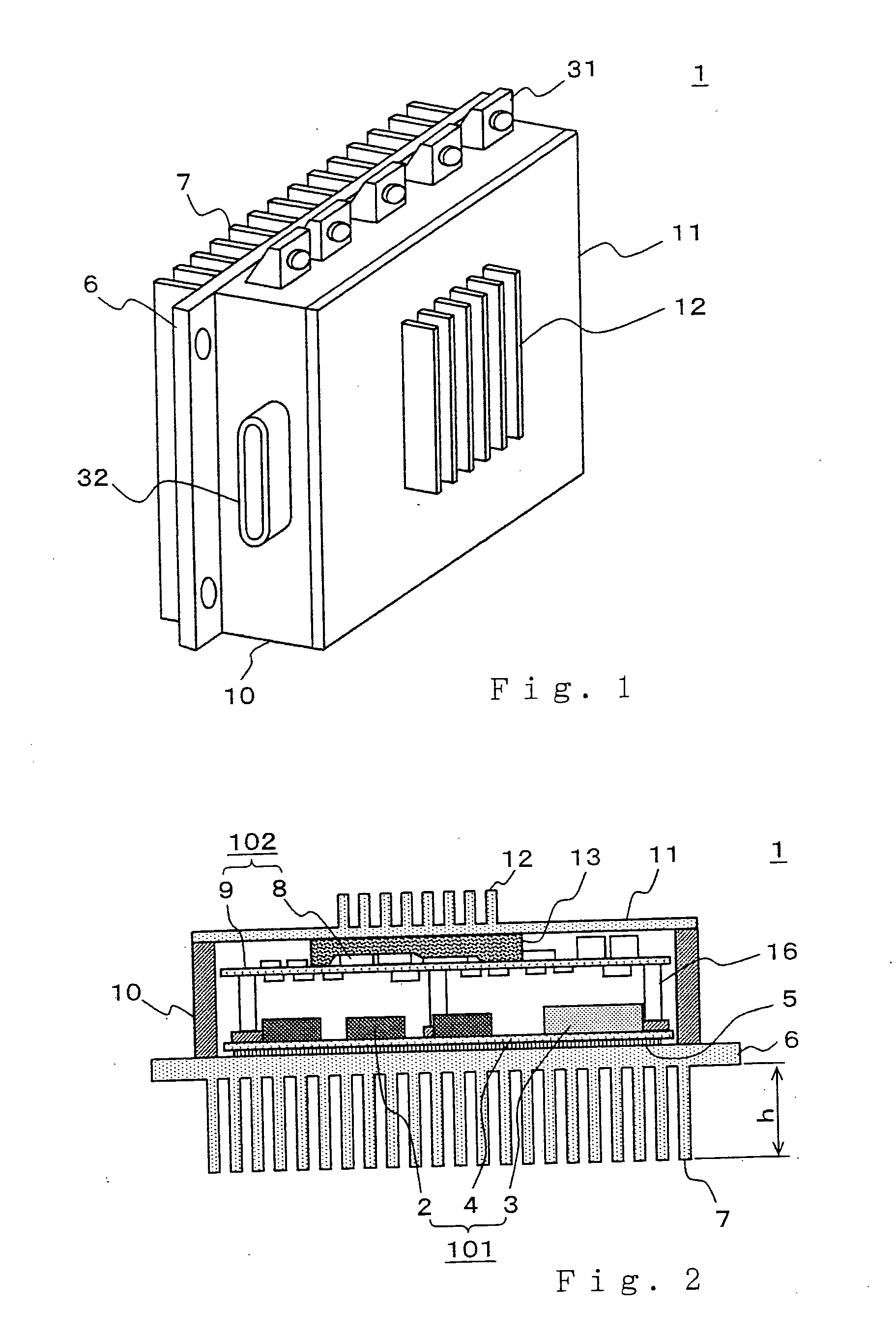
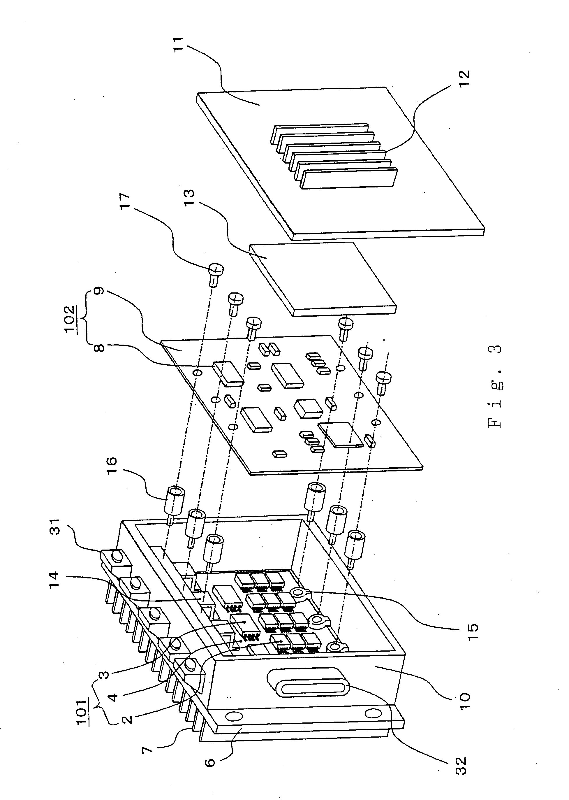
[0025] Hereinafter, a vehicular power converter according to Embodiment 1 will be described with reference to the accompanying drawings. FIG. 1 is a perspective view showing an outline view of a vehicular power converter according to Embodiment 1; FIG. 2 is a sectional view thereof; and FIG. 3 is an exploded perspective view.

[0026] First, the outline of a power converter 1, as shown in FIG. 1, includes a base plate 6 having a first heat exchange section 7, in which a power circuit section to be described later is mounted; a peripheral wall surface member 10 for placing a power circuit section and a control circuit section to be described later; and a cover 11 having a second heat exchange section 12. An external terminal 31, which is a conductive member for electrically coupling in and out of the power converter 1, and a signal connector 32 are mounted on the peripheral wall surface member 10.

[0027] Next, the internal configuration will be explained with reference to FIG. 2 and FI...

embodiment 2

[0044]FIG. 4 is an exploded perspective view of a vehicular power converter according to Embodiment 2 and FIG. 5 is a sectional view thereof. In the figures, those equivalent to FIG. 1 to FIG. 3 described in Embodiment 1 are shown by the same reference numbers and their description will not be repeated. One difference from Embodiment 1 is a heat shield member 18 which is provided between the power circuit section 101 and the control circuit section 102, and therefore, the heat shield member 18 will be mainly described.

[0045] As shown in the figures, mounting of the heat shield member 18 is carried out so that supporting members 19 are first mounted to protrusions 15 integrally formed on a peripheral wall surface member 10, then mounting pads 18a of the heat shield member 18 are aligned with the supporting members 19, and the heat shield member 18 is fixed with supporting members 20.

[0046] Next, mounting of the control circuit section 102 is carried out so that mounting holes of th...

embodiment 3

[0056]FIG. 6 is a partial sectional view of an essential part of a vehicular power converter according to Embodiment 3. The entire device is equivalent to FIG. 1 explained in Embodiment 1, and the entire sectional view except for that shown in FIG. 6 is equivalent to FIG. 2 of Embodiment 1 or FIG. 5 of Embodiment 2, and therefore, equivalent parts are shown by the same reference numbers and their description will not be repeated and only different parts will be mainly described.

[0057] As shown in the figure, electronic components 8 are mounted on both sides of a control substrate 9 which constitutes a control circuit section 102. The electronic components 8 generate heat when current is supplied, and an electronic component generating a particularly large amount of heat among the electronic components is denoted as heat generating components 22 to discriminate it. The heat generating component s 22 are, for example, a voltage regulator 22a of a power supply circuit section, a drive...


PUM


Abstract

To provide a vehicular power converter with high reliability by effectively radiating heat generated in a power circuit section and control circuit section without using a cooling fan. The vehicular power converter includes a power circuit section provided with a switching element; a control circuit section for controlling the switching element; and a housing for accommodating the power circuit section and the control circuit section, wherein a first heat conducting layer intervenes between a base plate having a first heat exchange section for cooling the power circuit section and the power circuit section; a second heat conducting layer intervenes between a cover having a second heat exchange section for cooling the control circuit section and the control circuit section; and the first heat exchange section and the second heat exchange section are disposed on one main surface side and on the other main surface side of an outer circumferential surface part of the housing, respectively.

Description

BACKGROUND OF THE INVENTION [0001] 1. Field of the Invention [0002] The present invention relates to a vehicular power converter which is mounted in a vehicle or the like and, more particularly, to a heat radiation structure of a power converter having a power circuit section and a control circuit section. [0003] 2. Description of the Related Art [0004] A power converter generally includes a power circuit section having a converter constituted by switching elements for converting a direct current to an alternating current of any frequency and a smoothing capacitor etc., and a control circuit section having a function for outputting a signal for controlling the switching elements and a function for electrical protection of the device. These sections are accommodated in a case. A power converter for regulating the input power of a three-phase motor incorporates two pairs of switching elements for each phase. [0005] Since a power circuit section is used for regulating the input power t...

Claims


Application Information

Patent Timeline
IPC IPC(8): H05K7/20H01L23/36H02M7/48
CPCH01L23/3677H01L25/162H01L25/165H01L2224/32225H02M7/003H05K7/20854H05K7/209H01L2924/3011H05K7/14322
Inventor KIKUCHI, MASAOSONODA, ISAOASAO, YOSHIHITOIPPOUSHI, SHIGETOSHI
Owner MITSUBISHI ELECTRIC CORP
Features
  • Generate Ideas
  • Intellectual Property
  • Life Sciences
  • Materials
  • Tech Scout
  • Unparalleled Data Quality
  • Higher Quality Content
  • 60% Fewer Hallucinations
Learn More